background image

GE Digital Energy 

Power Quality 


User manual 

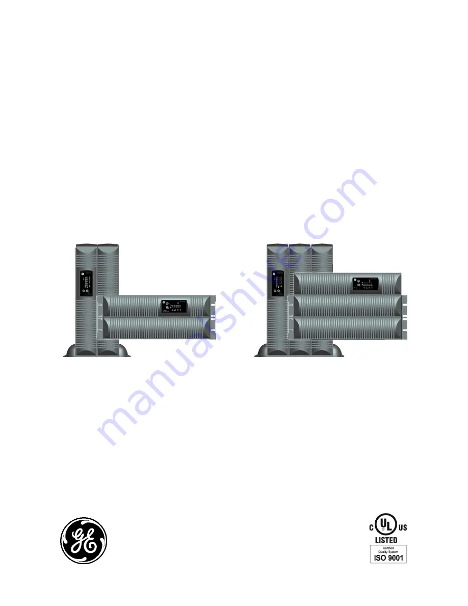
Digital Energy™ Uninterruptible Power Supply 

GT Series UPS 

5/6/8/10 kVA 


GT5000 RT / GT6000 RT 

GT8000 RT / GT10000 RT 


GE Digital Energy™ 

General Electric Company 

CH – 6595 Riazzino (Locarno) 

Switzerland 
T +41 (0)91 / 850 51 51 

F +41 (0)91 / 850 52 52 

www.GEDigitalEnergy.com 


imagination at work 

Summary of Contents for Digital Energy GT Series

Page 1: ...Uninterruptible Power Supply GT Series UPS 5 6 8 10 kVA GT5000 RT GT6000 RT GT8000 RT GT10000 RT GE Digital Energy General Electric Company CH 6595 Riazzino Locarno Switzerland T 41 0 91 850 51 51 F 41 0 91 850 52 52 www GEDigitalEnergy com imagination at work ...

Page 2: ...ue 09 01 2008 File name OPM_GTS_XUL_5K0_10K_XUS_V010 Revision 1 0 Identification No Up dating Revision Concern Date General Electric Digital Energy All rights reserved reproduction without permission prohibited The content of this manual may be subject to change without prior notice no liability can be accepted for any error or omission The illustrations and plans describing the equipment are inte...

Page 3: ... kVA 23 4 2 2 Start up of a 8 10 kVA 24 4 2 3 Start up of a parallel system 8 10 kVA models 24 4 3 Use normal operation 25 4 3 1 Normal operation conditions 25 4 3 2 Switching off 25 4 3 3 Maintenance Bypass 26 4 4 Use status and alarm indications 27 4 4 1 On bypass 28 4 4 2 On battery 28 4 4 3 Battery low end of runtime 28 4 4 4 Bypass out of limits 28 4 4 5 Overload 28 4 4 6 Replace battery 29 4...

Page 4: ...d in this manual may be changed without notice The instructions in this manual are for UPS models GT5000 RT GT6000 RT GT8000 RT and GT10000 RT Check your model number by looking at the top cover of your UPS Any difference in instructions is clearly indicated in the text for instance GT10000 RT 1 2 SAFETY WARNINGS AND SYMBOLS Safety warnings The text of this manual contains warnings to avoid risk t...

Page 5: ... WEIGHT of the UPS when downloading the UPS from the pallet Never try to lift the unit by yourself No liability can be accepted for any transport damage when the equipment is shipped in non original packaging Store the UPS in a dry location with the batteries in a fully charged state Storage temperature must be within 20 45 C 4 F and 113 F If the unit is stored for a period exceeding 3 months opti...

Page 6: ...in cards to properly qualified skilled and competent service personnel Qualified skilled personnel are persons who because of their training experience and position as well as their knowledge of appropriate standards regulations health and safety requirements and working conditions are authorized to be responsible for the safety of the equipment at all times whilst carrying out their normal duties...

Page 7: ...ormation concerning connecting requirements can be found on the rating label and in this document and shall be strictly observed 2 3 WARRANTY GE Digital Energy warrants that the standard products will be free of defects in materials and workmanship for a period of twenty four 24 months after seller s shipment date NOTE This warranty does not cover failures of the product that result from incorrect...

Page 8: ...trostatic sensitive and are for that reason easily damaged due to improper handling Avoid locations that are excessively humid near water near heat sources or in direct sunlight It is important that the unit has adequate ventilation Maintain air movement around and through the unit Do not block the air vents The ambient temperature should not exceed 40 C 104 F Optimal battery lifetime is obtained ...

Page 9: ...n power supply even if the UPS has not been switched on via the front panel 3 3 1 Tower installation preparations all models fig 3 3 1 a fig 3 3 1 b 1 On 5 6 kVA models align terminals on the backside of the PDU with UPS ones and slide PDU in the UPS fig 3 3 1 a 2 Assemble the plastic support stand and place them in the desired position 2 fig 3 3 1 b 3 3 1 c 3 Place the cabinet upright in to the p...

Page 10: ...ing the mounting brackets only fig 3 3 2 a fig 3 3 2 b fig 3 3 2 c 5 6 kVA 5 6 kVA 8 10 kVA NOTE Please consider the weight of the UPS see section 9 prior to installation to ensure the rack and floor are capable of supporting the weight For rack installation we recommend that the UPS is placed in the lower section of the rack Fit the unit and the battery into the rack cabinet with the help of a se...

Page 11: ...tery compartment aligning the rear connector to the front panel 2 fig 3 3 3 a 3 Slide the battery pack into the battery compartment until the rear connector is plugged with the UPS internal DC socket 4 Fix the battery cover by tightening screws 4 fig 3 3 3 b 5 Mount the front panels by pushing the plastic part into the appropriate holes 5 fig 3 3 3 c 6 Proceed with the UPS preparation fig 3 3 3 a ...

Page 12: ...mpartment 2 fig 3 3 4 a 3 Fix the 2 battery brackets with the screw set to hold battery packs into the cabinet 3 fig 3 3 4 a 4 Connect the UPS DC connectors of each battery pack 4 fig 3 3 4 a 5 Fix the battery grille in front of the battery compartment with 3 screws 5 fig 3 3 4 b 6 Mount the front panels by pushing the plastic part into the appropriate position 6 fig 3 3 4 c 7 Proceed with the UPS...

Page 13: ... pack fig 3 3 5 b At first start up the value of the total battery capacity has to be set with the UPS Monitoring software fig 3 3 5 a fig 3 3 5 b 5 6 kVA 5 6 kVA NOTE If further battery packs are used they connect via the previous battery pack Thus the cable provided is attached via the nearest socket connection on the existing battery cabinet fig 3 3 5 c fig 3 3 5 c 5 6 kVA NOTE When the UPS is ...

Page 14: ...rtment with 3 screws 5 fig 3 3 6 b 6 Mount the 2 battery front covers 6 fig 3 3 6 b fig 3 3 6 b 8 10 kVA 8 10 kVA The additional external battery pack connects to the UPS in the same way whether the UPS is being used in tower or rack mount format When used in tower format the UPS and additional battery packs can be mounted together in one set of mounting support stands fig 3 3 6 c Connect the cabl...

Page 15: ...ig 3 3 6 e 8 10 kVA NOTE When the UPS is connected to the mains and the battery pack is connected to the UPS the batteries start charging For best results allow the UPS to recharge the batteries during a period of approx 8 hours It is acceptable to use the UPS without first charging the battery but the runtime may be reduced modifications reserved 15 User manual GT Series 5 6 8 10 kVA UPS 1 0 US ...

Page 16: ...e and place the second winding also inside the ferrite bead fig 3 3 7 a 3 3 7 b 3 Close the ferrite bead such that the cable remains inside it fig 3 3 7 a 3 3 7 b fig 3 3 7 a fig 3 3 7 b You can now connect the DB9 port to a computer by connecting the previously prepared serial cable fig 3 3 7 c 3 3 7 d Additional signals can be read from the serial connector See section 5 1 for more information O...

Page 17: ...t Unit with standard Power Distribution Unit fig 3 3 8 a Unit with Optional PDU see section 6 6 1 fig 3 3 8 b Rear Panel 8 10 kVA 1 Input Output terminals see section 3 3 9 2 Input breaker 2pole 60A 250Vac 3 Maintenance Bypass see section 4 3 3 4 Output breaker 2pole 60A 250Vac 5 External battery connectors 6 SNMP card slot 7 DB9 Communication port 8 Fan Module 9 REPO Contacts see section 4 4 10 1...

Page 18: ...he input output cables using glands according to fig 3 3 9 c 4 Input Connect the mains supply wires to the terminals L1 L2 Line and N Neutral and the ground wire to terminal Ground connection is essential fig 3 3 9 d 5 Output Connect the load wires to the terminals L1 L2 Line and N Neutral and the ground wire to terminal Ground connection is essential fig 3 3 9 d fig 3 3 9 c 5 6 kVA 8 10 kVA NOTE ...

Page 19: ...tion 3 4 Otherwise proceed with section 4 fig 3 3 9 f fig 3 3 9 g 5 6 kVA 8 10 kVA NOTE The UPS output sockets are live as soon as the UPS is connected to the mains even if the UPS has not been switched on via the front panel For 5 6 kVA models an additional ground connection is required main ground can be removed with the PDU Connect the UPS case to the nearest available ground connection with an...

Page 20: ...d to the values mentioned in section 3 2 2 All outputs must be connected together supplying the load It is advised to install switches S 1 2 3 fig 3 4 1 in the output wiring in order to be able to isolate a unit from the remaining system for service and maintenance purposes 3 Use insulated copper input and output wiring rated 90 C 194 F wire size based on the ampere capacities given in Tables 310 ...

Page 21: ...fig 3 4 2 a 2 Connect the DB 15 parallel cable provided with the UPS to the parallel port fig 3 4 2 b and tighten it 3 One cable connects two UPS in parallel To connect a third UPS into the parallel system repeat the process as above fig 3 4 2 d 4 For a quick start of the system proceed with section 4 2 3 5 Each UPS needs a different configuration of the DIPswitch as identification of unit in the ...

Page 22: ...nce see section 4 4 4 for more details 7 LED alarm red on in case of alarm 8 LED bar runtime capacity the remaining available battery runtime for the actual load in of the maximum runtime with the actual load When the alarm LED is on this bar may show a combination of LEDs describing the Alarm cause see 4 4 1º LED 0 20 green 2º LED 21 40 green 3º LED 41 60 green 4º LED 61 80 green 5º LED 81 100 gr...

Page 23: ...e of the unit to position On fig 4 2 1 d The Mains available LED on the operating panel see section 4 1 is lighted on 6 Wait 45 seconds to allow the output voltage to stabilize 7 Press keypad UPS on for 1 second Within few seconds operation LED will be illuminated and bypass LED will be extinguished 8 Close the Output circuit breaker placed on the rear side of the unit see fig 4 2 1 c 9 The unit i...

Page 24: ... be switched on Load will be shown on load LED bar fig 4 2 2 a fig 4 2 2 b fig 4 2 2 c fig 4 2 2 d 8 10 kVA 8 10 kVA 8 10 kVA 8 10 kVA 4 2 3 Start up of a parallel system 8 10 kVA models 1 Ensure that all breakers on all the units of the system are off 2 In case external batteries are used switch on each circuit breaker fig 4 2 1 a 4 2 2 a 3 Ensure that all manual bypass switches are turned to UPS...

Page 25: ...ired e g for maintenance purposes proceed with steps 4 7 below 4 Turn the Output circuit breaker to position off fig 4 3 2 b 4 3 2 c 5 Turn the Input circuit breaker to position off fig 4 3 2 d 4 3 2 e 6 In case of external batteries are connected switch off the battery cabinet circuit breaker and disconnect battery cabling at the rear side of the UPS 7 Open all switches and breakers upstream to t...

Page 26: ... and maintenance can be done fig 4 3 3 a fig 4 3 3 b 5 6 kVA 8 10 kVA NOTE After the UPS is shutdown or in External Bypass condition the residual DC voltage in the unit will be eliminated within 5 minutes Once the maintenance is executed recover normal conditions with the following steps 1 Close the Input circuit breaker see section 4 2 1 4 2 2 2 Wait 45 seconds to allow the output voltage to stab...

Page 27: ... Overload warning 4 4 5 1 5 5 1 0 5 sec Battery not connected 4 5 0 4 Replace battery 4 4 6 1 3 0 4 1 60 sec Bypass out of limits 4 4 4 1 5 0 4 o On bypass 4 4 1 1 5 0 4 1 120 sec o On battery 4 4 2 1 5 0 4 Battery low 4 4 3 1 0 4 1 5 sec Fault on bypass 0 5 Fault stand by Operating modes and corresponding indications see 4 3 1 4 3 2 and 4 4 1 4 4 9 intermittent continuous 0 5 number of LEDs that ...

Page 28: ...d within 2 minutes after the battery low alarm started If only part of the output capacity of the UPS is used this period can be longer with aged batteries this period can be shorter When the batteries are fully discharged the UPS is no longer able to supply the connected equipment and eventually output power is lost 4 4 4 Bypass out of limits The mains voltage or mains frequency is outside bypass...

Page 29: ...ection 4 4 5 1 4 sec General Alarm 1 60 sec Battery test failed see section 4 5 1 120 sec On bypass see section 4 4 1 4 4 8 Fault mode The UPS may be in fault mode if the following failure occurred Indicators on Battery Charge Bar Fault Situation LED 1 LED 2 LED 3 LED 4 LED 5 Buzzer Charger Over voltage 1 4 sec Output Short Circuit 1 4 sec Negative Power Overload 1 0 5 sec Over temperature 1 4 sec...

Page 30: ...s activated thus depending on the used switch the connection must be restored by closing or opening the contact Press UPS off button 2 times within 4 seconds to be able to restart the unit 4 4 11 No load shutdown If no load shutdown is enabled the load is less than 5 and in case of utility failure the UPS will switch off avoiding deep discharge of the batteries and output power is lost No load shu...

Page 31: ...sponding alarm will be generated see section 4 4 6 4 4 7 Deep battery test A deep battery test will update the runtime calculation and may be started via the UPS monitoring software The test will start only if the battery charge level is higher than 90 and the load must be at least 20 of the nominal rating The runtime calculation will be updated only if the test can run uninterrupted till complete...

Page 32: ...he UPS operates in bypass or stand by mode NOTE The change of some settings can cause the unit to switch from bypass to standby and output power is lost For more information regarding possible settings please refer to the Help manual of the UPS monitoring software 8 10 kVA 5 6 kVA fig 5 1 5 2 SNMP INTERFACE CARD OPTION This card allows the data interface to be connected directly to an Ethernet net...

Page 33: ...d from the UPS cabinet On 8 10 kVA models loosen the four mounting screws fig 6 1 b of the PDU cover and remove it 5 Remove PDU from UPS The unit is now ready for new PDU assembly fig 6 1 a fig 6 1 b 5 6 kVA 8 10 kVA 6 On 5 6 kVA models align terminals on the backside of the PDU with UPS ones and slide PDU in the UPS fig 6 1 c On 8 10 kVA connect terminals on the backside of the PDU with connectio...

Page 34: ...ndition of the new batteries the new runtime calculations may temporarily be unreliable Additional batteries increase the recharging time for the unit all other operational information is the same as for standard models The following table shows runtimes with up to 3 Battery Packs 1 Battery Pack is the normal configuration Unit Load Internal Batteries 1 Battery Pack 2 Battery Pack 3 Battery Pack 1...

Page 35: ... from battery replacement refer maintenance and service work to qualified and skilled personnel only Refer to section 1 2 for further details 7 3 RECYCLING THE UPS AT THE END OF SERVICE LIFE NOTE This product has been designed to respect the environment using materials and components respecting eco design rules It does not contain CFCs Carbon Fluorine Chloride of HCFCs Halogen Carbon Fluorine Chlo...

Page 36: ...nly the same type and size Never short the battery terminals Shorting may cause the battery to burn When working with batteries remove watches rings or other metal objects and only use insulated tools Avoid charging in a sealed container Proper disposal of batteries is required refer to your local codes for disposal requirements Never dispose batteries in fire they may explode Never disassemble or...

Page 37: ...uring this operation and consider the weight of the battery 4 Unpack the new battery pack from its carton box 5 Place the battery pack in front of the battery compartment aligning the rear connector to the front panel see section 3 3 3 6 Slide the battery pack into the battery compartment until the rear connector is plugged with the UPS internal DC socket 7 Fix the battery grille by tightening scr...

Page 38: ...e them out fig 7 4 2 b Be careful during this operation and consider the weight of the battery 5 Unpack the 2 new battery packs from their carton boxes 6 Place the battery packs side by side in the battery compartment 7 Fix the 2 battery brackets with the screw set to hold battery packs into the cabinet see section 3 3 4 8 Connect the DC connectors of each battery pack 9 Fix the battery grille in ...

Page 39: ... module see section 3 3 3 5 Slide optional PDU into new power module and fix the three mounting screws fig 7 5 1 a 6 Switch the UPS back to normal operation see section 4 3 3 for further details fig 7 5 1 a fig 7 5 1 b 5 6 kVA 7 5 2 Power unit replacement for 8 10 kVA models 1 Switch the UPS to manual bypass see section 4 3 3 for further details 2 Remove the 3 front covers 2 fig 7 5 2 a 3 Loosen t...

Page 40: ... voltage present Read section 4 4 2 UPS on battery Mains indicator not illuminating mains voltage present acoustic alarm intermittent Input fuse blown or circuit breaker tripped Replace fuse or reset breaker UPS failure Contact UPS dealer or go to www GEDigitalEnergy com UPS over temperature Allow UPS to cool down Alarm LED illuminated continuous acoustic alarm Overload at UPS output Reduce UPS lo...

Page 41: ...verload capability fully protected against overload and short circuits Overload behavior during battery operation 130 during 10 seconds 130 during 1 minute 200 during 2 seconds 200 during 5 seconds Overload behavior during bypass operation depends on rating of thermal circuit breaker overload protection 125 of TCB value for 200 seconds 110 for 300 seconds 200 of TCB value for 10 seconds 130 for 30...

Reviews: