GEH-3944B
INSTRUCTIONS
Decashield
®
400 Luminaire
GENERAL
This luminaire is designed for outdoor lighting ap-
plications, and should not be used in areas of limited
ventilation, or in high ambient temperature enclosures; it
should be installed and maintained according to following
recommendations.
UNPACKING
This luminaire has been properly packed so that no parts
should have been damaged during transit. Inspect to
confirm.
INSTALLATION
REFLECTOR ROTATION—Reflectors which have
internal sockets may be rotated such that socket is in any of
four positions. This allows variations in beam aiming. To
rotate reflector follow procedure below.
1. Rotation best accomplished before mounting luminaire .
2. Remove four screws which attach reflector to brackets.
Ballast compartment barrier is also removed.
3. Rotate reflector to desired position, being careful not to
twist socket lead wires.
4. Reattach reflector by inserting two screws at latch end of
luminaire first.
5. Reposition ballast compartment barrier and insert two
rear screws, reaching under reflector to position reflector
brackets as necessary.
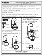
MOUNTING
Two types of mounting are available for luminaire:
A. ARCHITECTURAL MOUNTING: (Arm)
Use with square poles pre-drilled per Figure 1.
To facilitate mounting, internal tray may be removed by
unplugging wiring connectors, removing shipping screw
(not key-holed) and loosening all key-holed (2) and slotted
(2) screws. After mounting, replace tray.
1. Install nut plate (see Figure 2) inside pre-drilled pole.
Secure with screw provided.
2. Install two (2) studs ensuring full penetration of nuts on
nut plate.
3. Align inside of mounting arm with studs and slide it into
place against pole.
4. Remove luminaire door by pushing outward on latches,
and hinges, while supporting door. Remove ballast
barrier by loosening reflector screws.
5. Install luminaire and secure with flat washers and
locknuts provided (See Figure 3). Align as nuts tight-
ened.
CAUTION: Ensure that nuts fully engage the two
studs. Correct tightening of stud nuts is important
to ensure proper function of mounting system.
Torque nuts to 18-22 foot-pounds.
B. INTERNAL SLIPFITTER MOUNTING: (pipe bracket)
NOTE:
The pipe clamp accommodates 1-1/4-inch
through 2-inch ID pipe brackets.
WARNING
Risk of electric shock
•
Turn power off before servicing
–
see instructions
CAUTION
Unit will fall if not installed properly
•
Follow installation instructions
NOTE:
Power leads should be pulled as mounting
parts are assembled, verifying that leads are free
and not pinched. Ballast voltage selection is best
accomplished before mounting luminaire. See
“Wiring” for instruction.
READ THOROUGHLY BEFORE INSTALLING
Figure 1
Figure 2
These instructions do not purport to cover all details or variations in equipment nor to provide for every possible contingency to be met in connection with installation, operation or
maintenance. Should further information be desired or should particular problems arise which are not covered sufficiently for the purchaser’s purposes, the matter should be referred
to GE Lighting Solutions.
g
GE
Lighting Solutions