


466-1994B • August 2005
Copyright © 2005, GE Security Inc.
SuperBus® 2000 Wireless Gateway Module
Installation Instructions
Product summary
The SuperBus
®
2000 Wireless Gateway Module allows
customers to control and monitor their Concord
™
(v2.6-later),
Concord 4, and Concord Express (v4) systems from the
Alarm.com Web site. Through a wireless two-way paging
network, customers can control such features as security, notifi-
cations, history, and automation.
In addition to the wireless paging network, Concord owners may
also receive system event notifications by e-mail, pager, or
phone.
Note:
For UL Listed Concord installations, the Alarm.com website
can be used as an ancillary device for reporting, but
cannot be used for controlling the security system.
The module interfaces with Concord panel data buses and is
powered by the panel or an auxiliary 12V DC power supply.
Status LEDs indicate bus and paging network communications
and supervised zone inputs allow you to connect hardwire
contacts.
For added security, a magnet and reed switch (not included) can
be installed for tamper protection.
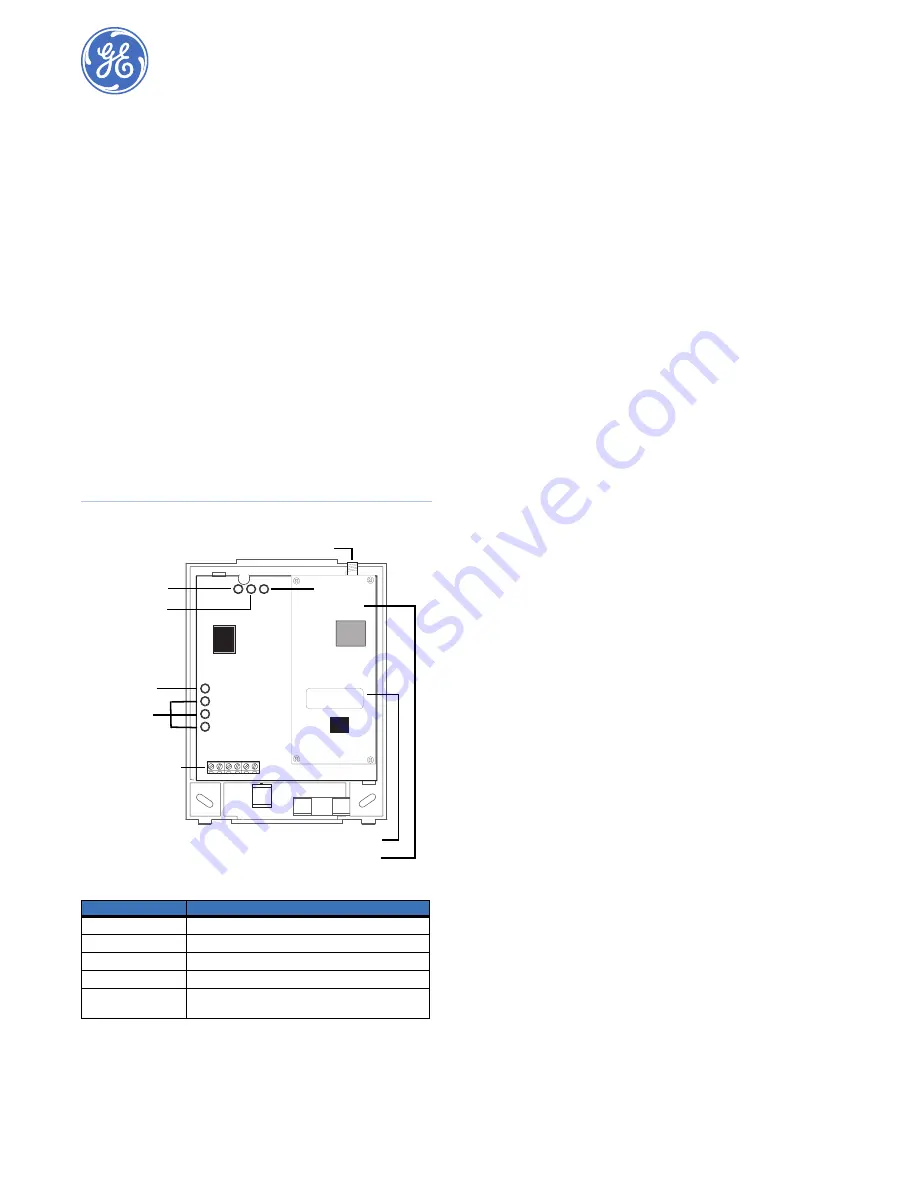
Figure 1. Wireless Gateway Module Main Components
Before installation
Before installing any Wireless Gateway, you must:
1.
Create the Alarm.com customer account prior to installing
the Wireless Gateway by logging into the Alarm.com dealer
website at the following location:
https://www.alarm.com/dealer
to become a registered
Alarm.com dealer/installer.
2.
Create the account at least 24 hours before installation to
ensure that the wireless module is activated properly on the
wireless network.
Creating a new account
To create a new account, do the following:
1.
Open a web browser and enter the Alarm.com dealer
website URL:
https://www.alarm.com/dealer
2.
Enter your dealer login and password and press
GO
.
3.
Click the
Check Coverage
link at the top of the page to
check wireless coverage at the install location. If the loca-
tion has full coverage, proceed with the next steps. If
coverage is uncertain, you may contact Alarm.com for more
details.
4.
Click the
Customers
link on the menu bar. Then click
Create Customer
.
5.
Enter the required customer information
Note:
Ensure the customer e-mail address is entered
correctly. Alarm.com sends a confirmation message,
and a list of account changes, to the customer via e-
mail.
6.
Click
Next
.
Step Two, Create Customer’s Login
will appear.
Follow the directions as stated. You may click on
Automat-
ically Generate Login
to have a login assigned to you.
7.
Click
Next
.
Step Three, System Location
will appear. If the
system is installed at the address provided at
Step One
Customer Information
, click
Yes
. If the system is installed at
an address different from the one provided in
Step One
Customer Information
, click
No
and enter the correct
address and time zone where the system is to be installed.
It’s important that you enter the correct system location
address at this step.
8.
Click
Next
.
Step Four Panel Information
will appear. In the
Modem Serial #
dialog box, enter the 10-character ID found
on the gateway you purchased (see serial number label in
Figure 1
). If you are unable to proceed with the modem
serial number, contact Alarm.com.
9.
Select
Concord
in the
Panel Type
list box.
10. Click
Next
. The
Confirmation
screen will appear. Review
the customer information. If you need to change any of the
information, click the
Edit
link next to the field you want to
update.
11. Click
Done
. The
Account Creation Successful
screen will
appear. Click
View and Print Welcome Letter
. Print two
copies of the welcome letter; one for the customer and one
for your records. The letter includes the customer’s login,
temporary password, and instructions on how to get started.
Also, a confirmation message is sent via e-mail to the
address entered in
Step One: Customer Information
. The
message contains a user confirmation number to be entered
during initial log on to the Alarm.com website.
Note:
If you leave the
Account Creation Successful
screen
without printing a welcome letter, you must click on
the
Customer
Tab, choose the
Customer Support
tab, and search for and click on the customer that
needs a New Welcome Letter. On the customer
information page that appears, select the
New
Table 1.
Component functions
Component
Function
Power LED
Indicates module power status.
Bus LED
Indicates panel bus communication.
Auto LED
Indicates module/data transceiver communications.
Status LEDs
Indicate pager network communication status.
Wiring Terminals
Provide power, bus, and hardwire zone input connec-
tions.
Power LED
Bus LED
Auto LED
Unused LED
Status LEDs
Wiring terminals
Serial number label
Antenna jack
Wireless data transceiver


