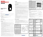
background image

t


+61 8 6108 0000


e


[email protected]


w


 gastech.com

t   

+61 8 6108 0000

    e   

[email protected]

    w  

gastech.com

Digital Gas Detector with  

Sounder Strobe

OPERATOR’S MANUAL

D

S

Summary of Contents for D-Guard2S

Page 1: ...t 61 8 6108 0000 e info gastech com w gastech com Digital Gas Detector with Sounder Strobe OPERATOR S MANUAL D S ...

Page 2: ...D Guard2 1 This Page Left Intentionally Blank ...

Page 3: ... 15 9 2 GENERAL INSTALLATION PRACTICES 16 9 3 DETECTOR DIMENSIONS AND MOUNTING ORIENTATION 16 9 4 INSTALLATION CONSIDERATIONS 17 9 4 1 Power supplies 17 9 4 2 Typical Connection to a power supply and controller 17 9 4 3 Maintaining Correct Operating Conditions 17 9 5 MOUNTING THE ENCLOSURE 18 9 5 1 Mounting Surfaces and Environment 18 9 5 2 Detector Location 19 9 6 ELECTRICAL CONNECTIONS 20 9 6 1 ...

Page 4: ...NSE TIME TEST FUNCTION 38 12 6 1 Running the DRT Checks 38 13 DETECTOR CONFIGURATION 39 13 1 SENSOR CONFIGURATIONS 39 13 1 1 Set Guard Band 39 13 1 2 Set Measurement Full Scale 40 13 1 3 Detector Type 40 13 1 4 Setting Span Gas Concentration 41 13 2 ALARM CONFIGURATION 41 13 2 1 Making Alarm Configuration Changes Alarm 1 shown 42 13 2 2 Alarm 1 Trip Level 42 13 2 3 Alarm 1 Hysteresis 42 13 2 4 Ala...

Page 5: ...DETAILED INSPECTIONS 52 17 3 GAS SENSING CELL REPLACEMENT 53 17 3 1 Removing the Detector Main Board 53 17 3 2 Replacing the Sensor 53 17 4 GENERAL DETECTOR REPAIR 54 17 5 DISPOSAL OF D GUARD2 COMPONENTS 54 18 APPENDIX A 55 18 1 OUTPUT CURRENT SIGNAL TOTAL LOOP RESISTANCE VS POWER SUPPLY VOLTAGE 55 18 1 1 Loop Resistance D Guard2 With Backlight Disabled loop at 22mA 55 18 1 2 Loop Resistance D Gua...

Page 6: ... H 64 25 1 PERFORMANCE SPECIFICATIONS 64 25 1 1 General Specifications 64 25 1 2 Methane Detector Specifications 64 25 1 3 Carbon Dioxide Detector Specifications 65 25 1 4 Electro Chemical Detector Specifications 65 25 1 5 Mechanical Environmental Specifications 65 ...

Page 7: ...logos are trademarks of their respective owners DISCLAIMER Under no circumstances will Gastech be liable for any claims losses or damages resulting from or arising out of the repair of or modification to the equipment by a party other than Gastech or its authorised service representatives or by operation or use of the equipment other than in accordance with the printed instructions provided by Gas...

Page 8: ...gure Gastech s policy is to perform all needed repairs to restore the instrument to full operating condition including reactivation or replacement of all out of warranty electrochemical cells You may send the unit freight prepaid to Gastech Pty Ltd 24 Baretta Rd Wangara Western Australia WA 6065 Attn Service Department Enclose the copy of your contact details Pack the instrument and all its access...

Page 9: ...vision 2 of Part V of the Act other than that implied by section 69 of the TPA the liability of the Company for such breach shall subject to section 68A 2 of the TPA be limited to one of the following as determined by the Company a the replacement of the Equipment or the supply of equivalent Equipment b the payment of the cost of replacing the Equipment or of acquiring equivalent Equipment 5 Subje...

Page 10: ... manual These notices are graded based upon the consequence of ignoring or incorrectly applying the information given Warning Significant risk to health and safety with the possibility of serious injury or death Caution Possibility of unsafe operation of D Guard2 and connected equipment Warranty of D Guard2 and connected equipment may be invalidated Note Additional information is provided to assis...

Page 11: ... purposes of risk reduction The detector is NOT designed to be used as the sole means of ensuring safety to personnel or equipment Must not be used in an oxygen enriched atmosphere Must not be modified in any manner As supplied the unit is constructed in accordance with and is compliant with the quality and performance standards against which it has been designed and tested Modification to its con...

Page 12: ...ct variant and the sensor type fitted The detectors carry the following information as part of its serial number identification label These makings provide information identifying the gas type serial number and its IP rating Label Details model number and IP rating will vary depending upon the model type 65 1080G xxx Base model IP66 67 68 65 1080R xxx Relay option fitted IP66 67 68 65 1080S xxx Re...

Page 13: ...place Examine all shipping boxes and protective packaging for items attached to them especially if the wrapping are to be discarded 4 2 Inspection Equipment that is found to be damaged or appears to have been modified in any manner must not be used Please contact Gastech if the equipment is suspected to be different than that ordered or if it does not match the published specifications 4 3 Storage...

Page 14: ... Equipment as supplied has been manufactured within the controls of relevant International and or Australian Standards and state legislative requirements Equipment identified within this manual has been designed for a specific purpose therefore any modification or damage to it must be reported to the manufacturer to allow for repair or replacement The instructions within this manual must be observ...

Page 15: ...lidated End users may change the gas measurement range and displayed gas name via the configuration menus and or HART communications however Gastech will not accept responsibility for nor accept liability for damage or injury caused by instruments rendered unsuitable for any particular application following such changes The facility for configuring the detector from within its operating system is ...

Page 16: ...he following components Gas Detector assembly User Manual Combined enclosure splashguard key and calibration magnet Manufacturing Quality certificate If the received package is incomplete please contact Gastech or the distributor that supplied the product Refer to Section 4 for unpacking and storage information ...

Page 17: ...as ventilation that affect the rate at which diffusion occurs In most cases over a long enough time the concentration of gas anywhere within the space will have equal concentration However in areas with enclosed spaces with poor ventilation gas may pool in higher concentrations if the rate of gas leakage into the space is greater than the rate of diffusion out of it Pooling can occur in roof space...

Page 18: ...cations engineer Ensure that the information in sections 11 to 19 plus Appendix A are understood It is extremely important that the functionality of the detector is fully understood in order to reduce the likelihood of creating hazardous situations and risks due to a malfunctioning detector or gas monitoring system If in doubt as to the functionality of the detector or the implications of incorrec...

Page 19: ...n which would prevent the passage of gas into the internal detector cell Prevent water and dust accumulation from affecting operation by mounting the sensor unit with the gas entry port pointing forwards or downward Do not install the instrument with the gas entry port facing upwards as this may allow the collection of water or dust to prevent gas entering the sensor Do not leave the splash guard ...

Page 20: ...the detector input terminals may prevent the full 3 3mA 22mA signalling range being available at the system controller input 9 4 2 Typical Connection to a power supply and controller Power supply Sensor Controller 9 4 3 Maintaining Correct Operating Conditions When handling the D Guard2 during installation great care must be taken to not damage any part of the system components since this may comp...

Page 21: ...d by mounting to an uneven surface Do not mount the detector to a surface using adhesive materials as this will not allow easy removal if necessary Additionally the use of adhesives on the enclosure will void the product warranty Adhesive fumes may also cause degradation to the gas sensing cell leading to premature failure Ensure that any surface coverings such as paint do not emit vapours Many pa...

Page 22: ...ases to be monitored can assist in deciding on optimal locations Permissible exposure levels are covered by various health and safety standards and are not reproduced in this manual A characteristic of significant interest is the buoyancy of the gas in air essentially whether it is more or less dense than air Knowing this can provide some indication of areas of possible pooling or areas near a poi...

Page 23: ...n connection is located to the bottom right of the circuit board as viewed from the rear of the board shown in the diagram below Removing the lid of the enclosure exposes a number of critical system elements that must be treated with care in order to maintain the operational integrity of the instrument Avoid touching the circuit board with hands or tools Avoid disturbing the sealing gasket that si...

Page 24: ...r when the lid is removed replaced Once the cable is positioned as required tighten the cable gland nut to hold the cable in place and create the waterproof seal When connecting direct to the main system board connections are first made to the power plug supplied with the instrument and the plug is then engaged into the power socket as shown above The plug and socket are keyed for correct alignmen...

Page 25: ...in gas reading due to electrical noise could be sufficiently large to cause the detector to enter an alarm state especially for instruments with low alarm ranges such as 1ppm or less With proper cable shielding noise can be dramatically reduced or eliminated allowing the response from the detector to properly represent the ambient gas conditions The normal detector response is steady with only sma...

Page 26: ...e to the instrument the front cover lid must be refitted correctly to maintain the IP66 68 ingress protection rating The enclosure base is fitted with a sealing gasket that is located in a groove that runs around the perimeter of the opening Before replacing the cover check that the gasket is present and seated correctly in the groove The gasket must not be twisted stretched or out of the groove a...

Page 27: ...ing on a system unless fully competent to do so and only with the knowledge that it is safe to do so Ensure that power to the detector is isolated at the controller side of the installation Visually check that detector mounting conforms to information given in this manual Check that all electrical connections within the detector s are correct per this manual Conductors should be marked and coded a...

Page 28: ...he site area where the detector is installed and must be used only as instructed in its operational manual by appropriately trained personnel Bump test procedures involve the use of toxic gases The gas concentrations used for test and calibration purposes are considered non harmful over the time period for which testing is likely to occur It is however the responsibility of the personnel carrying ...

Page 29: ...ot short the test points to ground or connect to the shield or the signal return terminals Doing so may cause damage to the detector electronics The bump test procedure should be carried out as follows example assumes a 0 100ppm H2S detector Decide on the appropriate method for observing the readings display current loop Remove the splash guard from the detector gas entry port the splash guard is ...

Page 30: ...der example 49 2 ppm Note the scale configuration of the detector under test e g 0 100ppm This is a 100ppm full scale detector Divide the test gas concentration by the detector full scale number in this case 49 2 100 giving 0 492 Multiply this number by 16 in this case 0 492 x 16 giving 7 872 Add 4 to the above result in this case 7 872 4 giving 11 872 The final result is the expected loop current...

Page 31: ...or all gas readings status messages and menu items The detector uses four magnetically sensitive switch devices that operate as user buttons keys The functionality of each button is context dependant based on the menu screen in use This system of soft keys is described in section 10 3 1 11 1 Detector Power Up For the first sixty seconds following power up D Guard2 displays the start up screen This...

Page 32: ... of the detector s target gas and its full scale measuring range Temperature This reading indicates the temperature within the detector body The temperature value may differ from ambient temperature by a few degrees Icon Locations Depending on the status of the detector and or specific menu pages these locations on the display will be occupied by status icons When an icon is not active its place i...

Page 33: ...e key and performs the action that is assigned to it at the time Return Home Present Location you are here Start Action Next Location where this key will take you Although the function of the keys change based on context there are only a small number of basic key function icons to remember There are also a number of fixed key function locations to simplify navigation to common screens such as the ...

Page 34: ...tylus must be held on the padlock icon continuously for a few seconds Depending upon whether a pass code has been set the next screen will either be the menu choice bars CAL SET or the screen for entering the pass code Padlock Icon for 2 5 seconds Menu is unlocked To enter the pass code scroll each digit up or down A padlock icon will show once a code is entered Entering an incorrect code will mov...

Page 35: ...new This signal degradation can be observed as a baseline measurement shift either positive or negative Similarly the cell s sensitivity to gas will reduce with a corresponding reduction in output signal for a given gas concentration If left uncorrected eventually the detector will no longer operate reliably in detecting its intended gas In order to maintain accurate and reliable operation the det...

Page 36: ...ring this time the trend bar may be observed for a stable reading as D Guard2 checks for a stable reading If the baseline gas concentration is greater than 10 of the detector s full scale a warning to apply purge gas is displayed A flashing gas cylinder icon is also displayed The Run Auto Cal soft key will not operate at this stage If not already connected connect the purge gas supply to the detec...

Page 37: ...whether a reading is rising falling or has stabilised by just looking at the displayed numbers The trend indicator will settle at the middle position once the raw sensor signal has stabilised and sat within a narrow band of values for around 5 seconds Once the trend indication is in the centre position the reading can be deemed stable enough to calibrate within the detectors specified accuracy lim...

Page 38: ...ve Observing the trend indicator will show when the gas reading has stabilised If the marker is in the centre position then the auto span process can be started If the marker is not in the centre position the sensor has not stabilised and auto span is not possible To continue operate the Run Auto Cal soft key Running the Auto Span Process Unstable Reading Warning After the Run Auto Cal soft key ha...

Page 39: ...nual Span Calibration After entering the Span calibration screens 12 4 4 Performing a Manual Span Calibration When entering the span calibration functions the auto span page is the first one entered Operate the Manual Span soft key to move on to the manual span calibration pages Once in the manual span screen and span gas has been applied the warning messages and icons will extinguish The gas read...

Page 40: ... sensitive if the current loop value is close the ideal value Short dabs of the up and down keys should be sufficient to bring the value back into the correct range Each time a change is made the home icon will change to the save icon One a value is saved the icon will revert to the home icon Further changes will again show the save icon The final value must be 4 00mA 0 01mA From the 4mA calibrati...

Page 41: ...n in the upper status banner Once test gas is applied the test begins automatically A message indicating the test is running is displayed Note it is absolutely essential to use the same span gas concentration each time this test is carried out This gas concentration must be set in the user calibration gas setup menu see section 12 1 4 If the same gas concentration is not used for each test the res...

Page 42: ...main Sensor setup screen is shown Select the SETTINGS soft key to start sensor configuration 13 1 1 Set Guard Band This setting allows the user to enable or disable the measurement guard band or zero suppression that assists in keeping the detector s baseline readings stable This suppression band is hard coded into D Guard2 and holds the readings at zero only whilst they are close to a real zero p...

Page 43: ...value than the default Increments are in units of 5ppm Note that if the full scale range is set too high for the current detector gain setting readings may become unstable Gas type is selected by the use of the up and down soft keys When a change is made the home icon changes to the save icon When the changes are saved the detector reboots to make the changes effective 13 1 3 Detector Type This se...

Page 44: ... reverts to the back icon allowing the previous setup function to be accessed if required To move to the Set Auto Zero screen operate the NEXT PARAMETER soft key To return home keep pressing the back soft key until the main sensor setup screen is displayed with the home icon showing 13 2 Alarm Configuration D Guard2 contains 2 gas concentration based alarms that provide indication that the measure...

Page 45: ... decrease the value The keys are accelerated to make the increments decrements move more quickly as the key is held To move back to the previous screen operate the BACK arrow soft key To move to the next parameter to change use the NEXT PARAMETER soft key Note if these keys are operated before the save icon is visible any changes made will not be saved Alarm 1 Trip Level Adjusted 13 2 3 Alarm 1 Hy...

Page 46: ...hanges will return the back arrow icon to the save icon Use the NEXT PARAMETER soft key to move to the next parameter to change Alarm Normal State Alarm Normal State sets whether a relay when fitted is in an energised or de energised condition under normal non alarm operating conditions The default is always normally energised since this provides failsafe indication of power failure to the detecto...

Page 47: ...etc Data Setup is accessed from the Quick Nav Screen 13 3 1 HART Setup Main Screen To access the HART data setup unlock the menu and operate the DATA soft key The main HART setup page displays the features that may be configured by the user Operate the SETTINGS soft key to start configuration 13 3 2 Turning HART Communications On or OFF Alarm 1 Latching Changed 13 2 7 Alarm 2 Current Settings Scre...

Page 48: ...or is operating in multi drop mode the fixed current loop value is indicated 13 4 System Configuration The system configuration screen allows configuration of the detector in a general sense such as detector isolation System Setup is accessed from the Quick Nav Screen 13 4 1 SYSTEM Setup Main Screen To access the SYSTEM data setup unlock the menu and operate the SYSTEM soft key The main SYSTEM set...

Page 49: ...he detector display can be set to appear as normal black on white images or as an inverted white on black image Changes are automatically saved 13 4 5 Sensor Temperature Compensation Sensor temperature compensation may be turned on or off as required Compensation against temperature changes is optimised for the sensors supplied with the detector and those supplied by Gastech Changing to sensor typ...

Page 50: ... displayed by four dashed markers in place of the readout Additionally the warning triangle and sensor fault icons are displayed since an over range condition can also be the result of a sensor failure Whilst the fault condition is occurring both icons will be displayed If the fault clears the warning icon remains in place to indicate that a fault log is active If the gas sensing element is produc...

Page 51: ...sor life remaining can be viewed on the detector information screen This fault is cleared by changing the sensor re calibrating the detector and resetting the sensor life counter 14 2 Fault Log And Information Screens 14 2 1 Detector Fault Log 14 2 2 Detector Information Screen The detector information screen contains the units serial number the date of manufacture hardware and firmware revisions ...

Page 52: ...ll signal this via a message in the lower status bar Additionally a static alarm bell icon will be displayed If the detector has relays fitted the warn relay will activate The behaviour of the alarm bell icon will depend on whether latching or non latching alarms have been configured If the measured gas concentration reaches the set point programmed into the detector for a danger condition the det...

Page 53: ...ors with local sounders and flashing beacons using the internal relay contacts these will be switched off for the ten minute period The inverse displayed bell icon will remain on the display to indicate that an alarm event has occurred After ten minutes the alarm state will be re activated if the alarm conditions are still present If an alarm has been triggered and the detector is set to latched a...

Page 54: ...ications port waterproof cap and plug the data connector into the port D Guard2 is by default set to polling address 0 and is set for point to point variable current loop operation D guard2 does not use Device Description type files and will be discovered as a generic device to a field communicator Once successful communication has been established the HART communication icon will start to flash r...

Page 55: ...rom water or contaminant ingress Check that door seals are in good condition Verify that labels fixed to equipment such as enclosures wall boxes and cables are present and in good condition allowing clear visibility of the information and identification they convey Verify that no unauthorised modifications have been carried out on equipment 17 2 Hands On Detailed Inspections More detailed inspecti...

Page 56: ...17 3 1 Removing the Detector Main Board To gain access to the sensor follow the steps given below Note ensure that this is only done by a suitably trained or qualified person It is strongly advised to wear an antistatic wristband and use an antistatic mat to place the detector PCB onto when working on replacing the sensor Remove the four lid retaining screws Unplug the power cable from its PCB soc...

Page 57: ...d of its service life it must not be treated as general waste The electro chemical cells used to detect gas contain substances that could potentially create an environmental hazard Under no circumstances should the cells be incinerated by the user since they could release toxic fumes When cells are replaced by Gastech Gastech will properly dispose of the used items Disposal of the electronics encl...

Page 58: ...to operate safely with the ability to drive the loop to 22mA fault signalling Incorrect allowance for system resistances and power supply voltages may result in the detector being unable to correctly signal the measured gas concentration The graphs below shows the relationship between detector power supply voltage output and maximum loop resistance for both Group I and Group II versions of D Guard...

Page 59: ...ption for standalone operation Additionally The D Guard2 G can be ordered with an optional relay board and sounder combination D Guard2 S part number 65 1080S xxx 19 1 1 Relay Board Functionality Current Loop Jumper Siren Connector Power Supply and Current Loop Power Supply to Main Detector Board Alarm 2 Relay Alarm 1 Relay Fault Relay Alarm 2 Siren Jumper Alarm 1 Siren Jumper ...

Page 60: ... alarm 1 threshold setting NC and NO connections apply to normally de energised relay settings For normally energised relays the function of NC and NO are reversed Alarm 2 Second alarm relay Changes state when measured gas level exceeds the alarm 2 threshold setting NC and NO connections apply to normally de energised relay settings For normally energised relays the function of NC and NO are rever...

Page 61: ... 2 Relay Board Connections 19 2 1 Current Loop Connection Scheme 19 2 2 Stand Alone Connection Scheme Relay Board Connection Current loop configuration Relay Board Connection Standalone configuration Connect to Siren ...

Page 62: ...er supply voltages are present it may be required to disable the backlight LEDs to gain additional voltage compliance for the current loop output to function up to 22mA Disabling the LEDs gives around 130 Ohms extra available loop resistance at 22mA or will allow the supply voltage to be operated 3 0V lower for a given loop resistance Determining whether the backlight link needs to be fitted requi...

Page 63: ...of the enclosure materials with exposure to these substances will depend on the nature of the application therefore the information given below is for guidance only Substance Gas Reaction Notes Ammonia 10 v v Severe reaction PPM levels of ammonia will give no problems Benzene Excellent Butane Excellent Calcium hyperchlorite Severe reaction Carbon Monoxide Excellent Carbon Tetrachloride Excellent C...

Page 64: ... 6 0 0 1 0 0 SO2 20 0 15 n a 4 1 1 NO2 10 0 25 100 5 n a 100 NO 50 8 0 110 n a 0 4 0 4 C2H4 400 52 0 5 30 0 0 Cl2 10 1 20 38 5 100 n a NH3 20 0 n a 0 0 0 1 0 2 0 2 CO2 5 0 0 0 0 0 1 0 0 0 03 As an example 400ppm of hydrogen sulphide would produce a response equivalent to 180ppm in a carbon monoxide sensor per the table value of 45 cross sensitivity 0 45 x 400ppm 180ppm equivalent response The actu...

Page 65: ...a toxic gas sensor to positive transients is about 3 times greater than for negative transients Infra Red sensors will respond equally to positive and negative pressure shifts Detectors should not be located in sealed rooms with doors that may be opened and closed rapidly or in locations where ventilation systems can create pressure pulses 23 4 Humidity The electrochemical cells used in D Guard2 d...

Page 66: ...D Guard2 63 24 APPENDIX G 24 1 System Menu Map ...

Page 67: ...ent Under any condition of operation or fault 30 mA GS 6 Minimum Supply Voltage at 20mA Minimum operating voltage at detector 13 0 VDC GS 7 Maximum Loop Resistance At Vpsu 28V with backlight see graph 720 Ohms GS 8 Absolute Maximum Supply Voltage Maximum supply voltage no damage to electronics All versions 30 VDC GS 9 Loop Error Signal low electronics fault Detected faults within hardware or softw...

Page 68: ...perating temperature limits 20 C to 50 C TSS 8 Operating humidity range 15 to 90 TSS 9 Operating pressure range 80kPa to 120kPa TSS 10 Pressure effects Negligible for steady state above or below 101 3kPa TSS 11 Humidity effects uncompensated Negligible for steady state above or below 60 RH TSS 12 Long term drift Zero Less than 0 01ppm to 0 5ppm per 12 months cell type and environment condition dep...

Reviews: