ECHOMAP™ PLUS 60/70/90
SERIES
Installation Instructions
Important Safety Information
WARNING
See the
Important Safety and Product Information
guide in the
product box for product warnings and other important
information.
When connecting the power cable, do not remove the in-line
fuse holder. To prevent the possibility of injury or product
damage caused by fire or overheating, the appropriate fuse
must be in place as indicated in the product specifications. In
addition, connecting the power cable without the appropriate
fuse in place voids the product warranty.
CAUTION
Always wear safety goggles, ear protection, and a dust mask
when drilling, cutting, or sanding.
NOTICE
When drilling or cutting, always check what is on the opposite
side of the surface.
To obtain the best performance and to avoid damage to your
boat, install the device according to these instructions.
Read all installation instructions before proceeding with the
installation. If you experience difficulty during the installation,
contact Garmin
®
Product Support.
Tools Needed
• Drill
• Drill bits
◦ Bail mount: drill bits appropriate for the surface and
hardware
◦ Swivel mount: 3 mm (
1
/
8
in.) drill bit
◦ Flush mount: 3 mm (
1
/
8
in.) and 9.5 mm (
3
/
8
in.) drill bits
• #2 Phillips screwdriver
• Jigsaw or rotary tool
• File and sandpaper
• Marine sealant (optional)
Mounting Considerations
You can mount the device using one of three methods.
Bail mount
: You can mount the device using the bail mount,
which allows you to tilt the device.
Swivel mount
: You can mount the device using the swivel base
and bail mount, which allows you to swivel and tilt the device.
Not available on the ECHOMAP Plus 90 models.
Flush mount
: You can mount the device in the dashboard,
which provides a more integrated installation.
Before permanently installing any part of your device, you
should plan the installation by determining the location of the
various components.
• The mounting location must provide a clear view of the
screen and access to the keys on the device.
• The mounting location must be sturdy enough to support the
device and the mount.
• The cables must be long enough to connect the components
to each other and to power.
• To avoid interference with a magnetic compass, do not install
the device closer to a compass than the compass-safe
distance value listed in the product specifications.
Fixed-Bail Mounting the Device
NOTICE
If you are mounting the bracket on fiberglass with screws, it is
recommended to use a countersink bit to drill a clearance
counterbore through only the top gel-coat layer. This will help to
avoid cracking in the gel-coat layer when the screws are
tightened.
Stainless-steel screws may bind when screwed into fiberglass
and overtightened. It is recommended to apply an anti-seize
lubricant on the screws before installing them.
1
Select the mounting hardware appropriate for your mounting
surface and for the bail-mount bracket.
2
Using the bail-mount bracket as a template, mark the pilot
holes through the screw holes.
3
Using a drill bit appropriate for the mounting hardware, drill
the four pilot holes.
4
Using the selected mounting hardware, secure the bail-mount
bracket to the mounting surface.
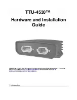
5
Install the bail-mount knobs
À
on the sides of the cradle.
6
Place the cradle into the bail-mount bracket
Á
, and tighten
the bail-mount knobs.
7
Connect each cable to a port on the cradle, using the locking
bracket or locking rings to secure the cables to the cradle
(
Installing the Cables and Connectors
).
Bail Mounting a Device with a Swivel Base
NOTICE
Only pan-head machine bolts or self-tapping screws should be
used to secure the swivel base. If you use screws with
countersunk heads, you may damage the mounting bracket.
Some models have the option of adding a swivel base to the bail
mount, so you can turn the device for a wider range of viewing
angles.
December 2017
190-02243-02_0B