Gamma 8500 Els, Owner'S Manual
Need help with your Gamma 8500 Els? Look no further! Get your hands on the comprehensive owner's manual, available for free download at manualshive.com. This detailed manual is the go-to resource for all your product-related queries, ensuring a seamless user experience and maximum product potential.
Share
Download


Reviews:
No comments
Related manuals for 8500 Els
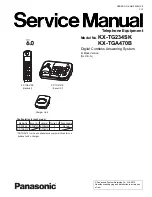
KX-TG234SK
Brand: Panasonic Pages: 99

95K32
Brand: Singer Pages: 9

39500FS
Brand: UnionSpecial Pages: 44

GC24698-BLHL
Brand: HIGHLEAD Pages: 35

TIG401
Brand: Rtech Pages: 24

FUTURA CE-200
Brand: Singer Pages: 100

44-26
Brand: Singer Pages: 47

Memory Craft 200E
Brand: Janome Pages: 54

MB-7e
Brand: Janome Pages: 115

Sfera 6-36 R/F
Brand: Necta Pages: 19

2622
Brand: Alfa Network Pages: 157

AMS-343B
Brand: JUKI Pages: 62

DDL-9000B-DS
Brand: JUKI Pages: 8

DLU-5494N-7
Brand: JUKI Pages: 4

DH4-B980
Brand: Brother Pages: 66

EF4-B641
Brand: Brother Pages: 56

DB2-B797
Brand: Brother Pages: 2

DB2-B797
Brand: Brother Pages: 28


