


G
AMATRONIC
E
LECTRONIC
I
NDUSTRIES
L
TD
.
17 Hartum St., PO Box 45029, Jerusalem 9777517, Israel
Tel: +972-2-588-8222 Fax: +972-2-582-8875
2MUM-PPCN/1
U
U
P
P
S
S
S
S
Y
Y
S
S
T
T
E
E
M
M
I
I
n
n
s
s
t
t
a
a
l
l
l
l
a
a
t
t
i
i
o
o
n
n
G
G
u
u
i
i
d
d
e
e
f
f
o
o
r
r
m
m
o
o
d
d
e
e
l
l
s
s
5
5
0
0
k
k
W
W
-
-
2
2
0
0
0
0
k
k
W
W
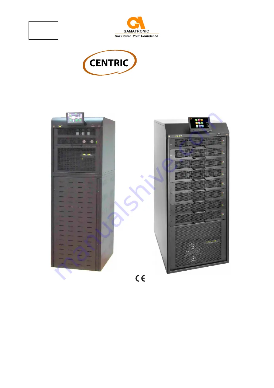
50 kVA model
with internal battery
200 kVA model
Release
2.8, December 2015
This manual
is for products
101SBD6*.


