


Summary of Contents for Recurring Nightmare
Page 4: ......
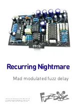
Introducing the FuzzDog Recurring Nightmare, a mind-bending audio device that delivers spine-chilling soundscapes. Unleash your inner nightmares with this ingenious creation. To unlock its full potential, simply download the free Instructions Manual at manualshive.com. Discover the mysteries behind this hauntingly beautiful product today!
Page 4: ......