Fujitsu M3096EX, Operator'S Manual
The Fujitsu M3096EX is a high-performance document scanner designed to optimize office productivity. Our website offers a comprehensive user manual that includes detailed Consumable Replacement and Cleaning Instructions. You can easily download this manual for free from our website, manualshive.com, to ensure proper maintenance and smooth operation of your scanner.
Share
Download


Reviews:
No comments
Related manuals for M3096EX

L24ei
Brand: Colortrac Pages: 92

V3200AP Series
Brand: Vicon Pages: 7

90334
Brand: Smart Optics Pages: 95

ESPE Lava Chairside Oral Scanner
Brand: 3M Pages: 118
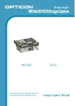
MDI-4 00/N210 Series
Brand: Opticon Pages: 16
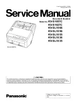
KV-S1057C
Brand: Panasonic Pages: 255
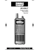
BC45XLT
Brand: Uniden Pages: 35

Xenon 1932
Brand: Honeywell Pages: 17

Xenon 1902h
Brand: Honeywell Pages: 15

Xenon 1902HC
Brand: Honeywell Pages: 16

Xenon 1500
Brand: Honeywell Pages: 176

LMK 2010
Brand: AMO Pages: 2

7761-K329
Brand: NCR Pages: 9

9650 USB
Brand: Visioneer Pages: 2

PaperPort OneTouch
Brand: Visioneer Pages: 31

PaperPort ix
Brand: Visioneer Pages: 54

OneTouch 8900
Brand: Visioneer Pages: 58

OneTouch 6600
Brand: Visioneer Pages: 54


