background image

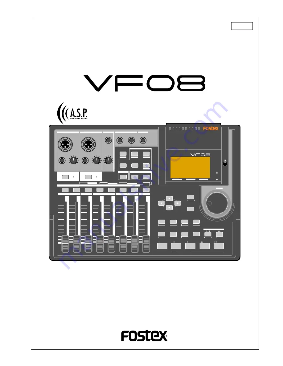
Digital Multitracker

Owner’s Manual

8588 002 000

(340292)

DIGITAL MULTITRACKER

LOCATE ABS 0

LOCATE REC END

SEL

TIMEBASE

CURSOR

PHANTOM

ACCESS

PEAK

CH ON/OFF

L

R

GUITAR

GUITAR

LINE

MIC

LINE

MIC

MIN

MAX

MASTERING

TRAINING

EFFECT

EQ

PAN

SCENE SEQ.

SCENE

TRACK

UNDO

SETUP

PUNCH

AUTO

LOOP

PITCH

SCRUB

VARI

F FWD

REWIND

PLAY

STOP

RECORD

EXIT

ENTER

TRIM

TRIM

WAVE FORM

MIX PARAMETER

PGM

FADER

MAP

ON/OFF

2TRK MODE

F1

F2

F3

SHIFT

EDIT

EDIT

EDIT

MARK

DELETE

LOCATE

FOOT SW

ST OUT

PHONES

INPUT A

BOUNCE MODE

INPUT B

+6

-10

-20

-40

-

-30

0

+6

-10

-20

-40

-

-30

0

+6

-10

-20

-40

-

-30

0

+6

-10

-20

-40

-

-30

0

+6

-10

-20

-40

-

-30

0

+6

-10

-20

-40

-

-30

0

+6

-10

-20

-40

-

-30

0

+6

-10

-20

-40

-

-30

0

PEAK

CH ON/OFF

2

3

4

5

6

7/8 2TRK

1

MASTER

TRACK STATUS / TRACK SEL

TRACK STATUS

RED

REC

GREEN

PLAY

OFF

MUTE

STATUS

/SEL

EJECT

    /YES

  /NO

SHUTTLE

JOG

UNBAL

UNBAL

BAL

BAL

F1

F2

F3

EDIT

/REDO

Summary of Contents for VF-08

Page 1: ...EWIND PLAY STOP RECORD EXIT ENTER TRIM TRIM WAVE FORM MIX PARAMETER PGM FADER MAP ON OFF 2TRK MODE F1 F2 F3 SHIFT EDIT EDIT EDIT MARK DELETE LOCATE FOOT SW ST OUT PHONES INPUT A BOUNCE MODE INPUT B 6 10 20 40 30 0 6 10 20 40 30 0 6 10 20 40 30 0 6 10 20 40 30 0 6 10 20 40 30 0 6 10 20 40 30 0 6 10 20 40 30 0 6 10 20 40 30 0 PEAK CH ON OFF 2 3 4 5 6 7 8 2TRK 1 MASTER TRACK STATUS TRACK SEL TRACK ST...

Page 2: ...ateral triangle is intended to alert the user to the presence of uninsulated dangerous voltage within the product s enclosure that may be of sufficient magnitude to constitute a risk of electric shock to persons The exclamation point within an equilateral triangle is intended to alert the user to the presence of important operating and maintenance servicing instructions in the literature accompany...

Page 3: ... Playback 26 Contents Basic recording recording onto two track 27 Preparation for recording 27 Recording 28 Playback 28 Mark function 29 Setting a mark on the fly 29 Locating a mark 29 Deleting a mark 29 ABS Locate 30 Punch In Out 30 Manual punch in out using the keys on the unit 30 Punch in out using the Foot Switch 30 Auto punch in out function 31 Mixing 33 Adjusting levels 33 Setting PAN positi...

Page 4: ...Slowing down the playback speed 70 Changing the pitch 70 Canceling the center positioned sound 70 Setting the cancel position 70 Boosting the bass sound 70 Playing along with the playback sound 70 Mastering mode 71 Selecting a program to be played back 71 On Off of mastering mode 71 Setting the mastering effects 72 On Off the mastering effects 72 Recording onto the master recorder 72 Effect librar...

Page 5: ...mpo 101 New Registering of Tempo 101 Correction of the Registered Tempo 102 Erasing of the Registered Tempo 102 Setting the Metronome function 102 Setting MIDI sync output signal 103 Setting an MTC frame rate 103 Setting an MTC offset value 104 Setting MTC offset mode 104 Setting the Slave mode 105 Setting the Slave type 105 Setting the Record Protect function 106 Setting Digital Input 107 Setting...

Page 6: ... MTC The internal metronome function can be used for recording a guide track The bar beat resolution function allows editing by beat the clock digit is omitted Up to 99 mark points can be set per each song You can locate any mark point or make the mark map of a scene Mixer Section Built in a high performance DSP multi effect processor employing the A S P Fostex Advanced Signal Processing technolog...

Page 7: ...e packaging or caused during transport It is prohibited by law to use any part of a CD recording or video images or audio data for which copyright is possessed by a third party for commercial purposes such as contents broadcasts sales or distribution any purpose other than for your personal pleasure Fostex is not responsible for any direct damage or indirect damage caused by using the VF08 Note on...

Page 8: ...itle with its program number appears at the top left of the normal screen as shown below The remain indicator shows how much recording time is left on the current hard disk The VF08 program is managed by a 24 hour time counter however the actual recording time left de pends on the available disk space The remain indicator appears on the LCD during re cording or on REC standby showing the rough re ...

Page 9: ...e called events With the VF08 you can create up to 512 events per track You cannot make any further recording when 512 events are created In the normal use 512 events are enough The VF08 can show the current number of events on the LCD It also shows a warning message if you are going to make recording when 512 events already exist You may resolve this problem by saving the program see Save Load of...

Page 10: ...he default setting however you can change to set it between bar 9 and bar 2 MTC MIDI Time Code runs in sync with the ABS time The MTC value h m s corresponding to ABS 0 can be set which is called MTC offset If you set the MTC offset to 01h00m00s the MTC will start from 01h00m00s and at the ABS 01h00m00s position the MTC value will be 02h00m00s The example below shows that the current position is a...

Page 11: ...RUB VARI F FWD REWIND PLAY STOP RECORD EXIT ENTER TRIM TRIM WAVE FORM MIX PARAMETER PGM FADER MAP ON OFF 2TRK MODE F1 F2 F3 SHIFT EDIT EDIT EDIT MARK DELETE LOCATE FOOT SW ST OUT PHONES INPUT A BOUNCE MODE INPUT B 6 10 20 40 30 0 6 10 20 40 30 0 6 10 20 40 30 0 6 10 20 40 30 0 6 10 20 40 30 0 6 10 20 40 30 0 6 10 20 40 30 0 6 10 20 40 30 0 PEAK CH ON OFF 2 3 4 5 6 7 8 2TRK 1 MASTER TRACK STATUS TR...

Page 12: ... A phantom power 48 V can be supplied for using a condenser microphone by setting the PHANTOM switch on the rear panel to ON When the INPUT A UNBAL connector is plugged the input from this connector is interrupted 3 INPUT A TRIM knob Controls the gain according to the signal from INPUT A You can adjust the gain to accept input signals between 50 dBV MIC and 2 dBV LINE 4 INPUT B UNBAL Unbalanced co...

Page 13: ...FF keys Each key is used to turn on and off of the corresponding channel When on the key illuminates See the following description for details about how to use each element 13 TRACK STATUS TRACK SEL keys While stopped each key is used to change the track status among OFF PLAY and REC READY During playback pressing the key switches between OFF and PLAY During recording you cannot change the track s...

Page 14: ...ing or deleting a scene memory press this key To view track fader positions press this key while de pressing the SHIFT key 18 MIX PARAMETER EFFECT ON OFF key When selecting the internal DSP effects adjusting the effect send levels selecting pre or post of the effect send or setting effect parameters press this key Select the track to be viewed or edited by pressing the corresponding TRACK STATUS T...

Page 15: ...gree 34 SHIFT key Used to activate the second shifted functions of keys and a dial Each shifted function is labeled in a while line boxes on the panel 35 LOCATE MARK key Each press of this key locates the previous mark point Pressing this key while holding down the SHIFT key stores the current position in the mark map 36 LOCATE DELETE key Each press of this key locates the next mark point Pressing...

Page 16: ...switches the time base shown on the screen among the following a ABS absolute time Absolute time from 00h00m00s to 23h59m59s b Bar Beat Clk Bar Beat Clock Bar Beat Clock according to the time signature and tempo information set in the internal tempo map c MTC MIDI Time Code MTC with or without an offset to the ABS time When a key icon is shown above F2 on the screen pressing this key while holding...

Page 17: ...t to the coaxial S P DIF digital output of an external digital device If the external device only provides the optical digital output use the Fostex COP 1 coaxial optical converter Connector RCA pin jack 54 MIDI OUTPUT connector Connects to the MIDI IN connector of an external MIDI device Mainly transmits MIDI information for synchronization such as MTC MIDI Time Code and MIDI clock with song posi...

Page 18: ...e current drive SCSI indicates the backup SCSI drive Press the ENTER YES key while IDE is flashed The menu to select the format type appears The display will appear as follows according to the previous format type represents the name of the drive The hard disk formatted in the Standard type upon newly formatting the hard disk will show Standard and Erase The hard disk formatted in the Quick type u...

Page 19: ... please contact the Fostex distributor in your territory Warning This section describes the procedures to replace the hard disk However we recommended that the customer ask the Fostex Customer Service Department to replace the VF08 hard disk Note that the product is not warranted for any malfunctions that may occur after the customer replaces the hard disk on their own Also note that Fostex will n...

Page 20: ...at are connected to the hard disk Gently hold the connector and slowly pull out After disconnecting the cables remove the panel that is fixing the hard disk Unscrew the four screws with a screwdriver as shown in the Figure Fix a new hard disk to the panel in the reverse order of removing the hard disk as performed earlier Connect the cables Then house the hard disk at the bottom of the main unit F...

Page 21: ...where the Standard is flashed The format type selected is set and Sure flashes Press the ENTER YES key while the RECORD key is depressed The formatting process is started The formatting process will take some time When the formatting is successfully completed Completed will light up on the display Press the EXIT NO key or STOP key to escape from the SETUP mode The Normal Screen appears indicating ...

Page 22: ...r Digital equipment CD MD DAT etc AC outlet Basic Recording and Playback This chapter describes the basics of recording and playback audio using the VF08 Sequencer PC w sequence software Top panel Connections of external equipment You can connect various sound sources and external devices to the input and output connectors of the VF08 as shown in the example below When making connection make sure ...

Page 23: ...ppears 2 Program number name With the initial setting P01 0001 0001 is a tentative name appears 3 Mark number name With the initial setting 00 ABS 0 appears showing that the current location is at the beginning of the program When the recorder starts running between the number and name is replaced with 4 Time base With the initial setting the ABS time base is selected You can change the time base ...

Page 24: ...e input connector the balanced XLR input connector is disconnected How to use condenser microphones When connecting a condenser microphone that needs the phantom power set the PHANTOM switch on the rear panel to ON Read the following notes carefully before using the phantom power Notes for using the phantom power Be sure to keep the following notes When connecting a condenser microphone to the bal...

Page 25: ...y desired track s In the following example we are going to record an electric guitar with an effect unit onto Track 1 Before starting set all the track faders 1 through 6 and 7 8 and the master fader to the lowest position and the TRIM knob to the leftmost position LINE Preparation for recording Connect the INPUT A UNBAL jack to the output of the effect unit whose input is connected to a guitar To...

Page 26: ...h as EQ You can add reverb or equalize the sound during mixdown When the recorder starts running the mark number and name shown on the top line of the screen changes as below showing that the current position is ahead of ABS 0 point To stop recording press the STOP key After showing Please Wait the LCD returns to the Nor mal screen Unarming a track To unarm a track press the flashing TRACK STA TUS...

Page 27: ...ing onto track 1 as described in the previous section let s make recording of a stereo sound source onto tracks 3 and 4 Preparation for recording Connect the INPUT A UNBAL and INPUT B UNBAL jacks to the L and R outputs of the stereo source re spectively Press the TRACK STATUS TRACK SEL keys of Tracks 3 and 4 The keys lighting in green change to flashing in red showing Tracks 3 and 4 are now armed ...

Page 28: ...layback levels by using the cor responding track faders If you find that the recording was not successfully made use the undo redo function and try recording again Track muting The playback level of each recorded track can be con trolled using the corresponding track fader You can mute the playback tracks by pressing the corresponding TRACK STATUS TRACK SEL keys except in the mix parameter edit mo...

Page 29: ...arked is entered in the mark map list see Recorder functions for details To enter another mark repeat step 1 above Note Marks are assigned in ascending order of ABS time For example even if you enter marks in order as shown in the upper diagram below the mark numbers are as signed as shown in the lower diagram Locating a mark Pressing key locates the previous mark In the example above each time yo...

Page 30: ...yback to recording while Punch out switches the transport mode from recording to playback The point at which a punch in is carried out is called a punch in point while the point at which a punch out is carried out is called a punch out point You can carry out the punch in out operation in 3 ways Manual punch in out using the keys on the unit Using the foot switch Model 8051 Auto punch in out funct...

Page 31: ...t at which you carry out the operation above is stored as the punch out point Note Set the punch in point earlier than the punch out point Setting the punch in out points numerically While the recorder is stopped you can set the in and out points by entering the time numerically While stopped press the AUTO PUNCH EDIT key while holding down the SHIFT key The screen for setting the punch in out poi...

Page 32: ... NO key 7 Performing auto punch in out recording After storing the punch in and out points you can perform the auto punch in out recording Press the AUTO PUNCH EDIT key to illuminate the key The auto punch mode is now active Locate the earlier position to the punch in point Press the RECORD key while holding down the PLAY key A take of auto punch in out recording starts and TAKE lights up on the s...

Page 33: ...y The pan setting screen is shown where Select TRK is blinking in the initial condition Press the TRACK STATUS TRACK SEL key of the de sired track or use the CURSOR keys to select the desired track The pan icon of the selected track is highlighted show ing that it is editable highlighted Blinking highlighted Set the pan position using the JOG dial The pan icon on the screen changes in real time ac...

Page 34: ...her tracks carry out step 2 and 3 above repeatedly Effect type setting Effect type setting The VF08 provides 38 effect types in the effect library You can select any one of the types depending on the usage See Mixer functions for details about the effect li brary Bring up the effect type setting screen and select the desired effect type by rotating the JOG dial While rotating the JOG dial the effe...

Page 35: ...rder while applying the dedicated mastering effects to the signal See Advanced Operation for details about the mastering mode Analog mixdown Connect the ST OUT L R jacks to the input jacks of your analog master recorder Set the recording level of the master recorder Start recording the master recorder and start playback of the VF08 from the beginning of the song When recording finishes stop both t...

Page 36: ...turning on the power the VF08 starts up while showing the unit information on the LCD display and then gets ready when the screen below appears This screen is called Normal Screen in which the program number and current recorder position are shown In the following example the default Program 1 P01 is loaded and the current position is the beginning ABS 00M 00S Operations while the Normal screen is...

Page 37: ... STATUS TRACK SEL keys on the panel flash If you have edited any track parameter for pan EQ or effect send setting after turning on the power last time the icon for the previously edited track is highlighted showing that it can be edited Select the desired track by pressing the correspond ing TRACK STATUS TRACK SEL key or using the CURSOR keys The pan icon of the selected track is highlighted indi...

Page 38: ...F library en try Hi Gain Pressing the CURSOR up key changes the blinking parameter in the reverse order Use the JOG dial to edit the parameter value The following values are available for each parameter Hi Gain Lo Gain ON OFF 18 dB through 0 dB to 18 dB in 1 dB steps The current EQ curve is shown graphically accord ing to the current values 18 dB through 0 dB to 18 dB in 1 dB steps The current EQ ...

Page 39: ...O HI 4 0 7 0 100Hz 6kHz L S H S L11 Perc Gain Freq Q LO HI 8 0 10 0 360Hz 5 4kHz L S H S L12 Tamb Gain Freq Q LO HI 5 0 3 0 100Hz 2 4kHz 0 1 6 3 L13 Fat_Bass Gain Freq Q LO HI 5 0 4 0 190Hz 2 4kHz 1 0 1 0 L14 Norm Bass Gain Freq Q LO HI 4 0 3 0 120Hz 1 3kHz 2 0 2 2 L15 Loud_Bass Gain Freq Q LO HI 3 0 4 0 340Hz 5kHz 0 9 H S L16 Bright_Pf Gain Freq Q LO HI 5 0 3 0 200Hz 1 3kHz L S 0 9 L17 Loud_Pf Ga...

Page 40: ... 1 L22 OverDrvEG Gain Freq Q LO HI 6 0 4 0 370Hz 3 6kHz L S 10 L23 Dist EG Gain Freq Q LO HI 3 0 12 0 230Hz 14kHz 0 7 H S L24 Metal_EG Gain Freq Q LO HI 9 0 8 0 100Hz 9kHz 0 7 1 2 L25 Stroke_AG Gain Freq Q LO HI 2 0 3 0 210Hz 9 4kHz L S 0 1 L26 Arpeg EAG Gain Freq Q LO HI 7 0 5 0 530Hz 4 4kHz 7 1 H S L27 Arpeg AG Gain Freq Q LO HI 3 0 4 0 125Hz 260Hz L S 2 2 L29 W WindSec Gain Freq Q LO HI 2 0 3 0...

Page 41: ...s on this Early Reflection Sound and how closely it can resemble the real echo The H F A is an algorithm that enables the effect unit to reproduce a clear and natural Early Re flection Sound by applying an ideal harmonic feed back to each delay module H D L P Hi Density Logarithmic Processing The reverb sounds consist of lots of small delay ele ments combined in a complex way which are produced by...

Page 42: ...K SEL key or using the CURSOR keys The icon of the selected track is highlighted indicat ing that you can edit it In the default settings the send levels for Tracks 1 through 6 are 00 while the level for Master is 80 Use the JOG dial to adjust the send level value The knob icon also rotates according to the level value When the level is set to 00 no signal is sent to the effect processor Editable ...

Page 43: ...ey to bring up the pre post set ting screen If you have not edited any track parameter for effect send EQ or pan setting after turning on the power last time the message prompting to select a track Select TRK blinks as well as the TRACK STATUS TRACK SEL keys for Tracks 1 through 6 on the panel flash If you have edited any track parameter for effect send EQ or pan setting after turning on the power...

Page 44: ...20 PresVOCAL REVERB Short reverberation with extended high frequency is added to the early reflections of an ideal vocal booth Since this adds sparkle to the sound it is effective when you wish to bring the vocal to the forefront L21 SoloVOCAL REVERB Plate like reverb is added to a spacious short delay This blends well with any genre of music L22 ArenaVOC REVERB Gentle reverb is added to spacious ...

Page 45: ...ers can be adjusted 1 Eff Level Adjust the effect return level 0 99 2 BPM Adjust the BPM Range 30 250 bpm 3 Note Select the note value for the delay Range 24 16 8T 16 8 4T 8 4 2T 4 2 2 1 24 16th note sextuplets 16 16th notes 8T 8th note triplets 16 dotted sixteenth notes 8 8th notes 4T quarter note triplets 8 dotted eighth notes 4 quarter notes 2T half note triplets 4 dotted quarter notes 2 half n...

Page 46: ...dulation delay Range 0 200 5 Feedback Adjust the number of modulation repeats Range 0 99 Delay pitch effect parameters parameter type DELAY PITCH For effect type 38 of the preceding Effect type table the following four parameters can be adjusted 1 Eff Level Adjust the effect return level 0 99 2 Pitct Adjust the amount of pitch shift Range 24 0 24 12 is one octave 24 is two octaves 3 Adjust Make fi...

Page 47: ...umber to which you want to store the current settings and press the TIME BASE SEL F2 key while holding down the SHIFT key In the following example S01 is selected The scene name of the program which you worked with before entering the scene memory mode is duplicated to the name of the selected scene number whose leftmost character blinks showing that it can be edited Enter the desired scene name b...

Page 48: ...ory is deleted and the scene name changes to Un defined showing that no memory is stored Press the EXIT NO key The display returns to the Normal screen Fader adjust After recalling a scene the recalled fader level usu ally does not match the current physical fader posi tion you can move the physical faders to match the current fader positions of the scene The following description is assumed that ...

Page 49: ...h the current marks are listed In the mark map example below only scene memory 00 is assigned to mark 00 Non means that no memory is assigned to the corresponding mark Hint You can view mark titles instead of mark positions in bar beat clock base or ABS time base in the mark map Pressing the TIME BASE SEL key while the mark map screen is shown switches mark positions and mark titles Select the des...

Page 50: ...scene sequence If you start playback while the scene sequence func tion is active ON the scenes will be recalled accord ing to the mark map Note When executing the scene sequence the fader positions may be recalled or not according to the fader recall mode setting in the setup mode the default is OFF For example if you set the fader recall mode to ON both the track and master faders are automatica...

Page 51: ...ssible at the speed between 1 and 64 times the normal speed Press the PLAY key to start playback Rotate the JOG SHUTTLE dial while holding down the SHIFT key Rotating the JOG SHUTTLE dial clockwise moves the position to the forward direction while rotating the dial counter clockwise moves the position to the backward direction According to the rotating degree the cueing speed varies among 1x 2x 4x...

Page 52: ...le scrubbing while the time value or bar beat of the current posi tion is shown in realtime If you want to scrub another track repeat steps 2 and 3 Storing the digital scrub point You can store the scrub point to the Start End or To point for track editing functions such as Copy Move Paste and Erase or the auto punch in point To store the scrub point to the Start point Press the SETUP F1 key while...

Page 53: ...ction is not active Note You can turn on or off the vari pitch function while stopped or during playback however you cannot turn on or off the function during recording Setting the speed You can adjust the speed while stopped or during playback however you cannot adjust the speed dur ing recording If you adjust the speed during play back with the vari pitch function active you can moni tor the res...

Page 54: ...position via the screen 3 Setting by marks Capturing the current position on the fly While stopped or running you can set the Start or End point at the point you capture Press the LOOP EDIT key while holding down the SHIFT key The display shows the loop screen in which you can set the Start and End points At the point where you want to set the Start point press the SETUP F1 key while holding down ...

Page 55: ...number and name Press the ENTER YES key The mark shown on the Start point value field starts blinking Use the JOG dial to select the desired mark and press the ENTER YES key The Start point is set to the selected mark while the display returns to the similar screen shown in step 2 above To edit the End point use the CURSOR down key to highlight the End point value and carry out the same operations...

Page 56: ...u can enter the program title by following the procedure described in How to enter a desired title below Note that you may use the program with the tentative title 0002 in this example if you do not need to en ter the desired one Anyway you may also enter edit the title later by the procedure described in Editing a program title on page 57 To use the program with the tentative title press the EXIT...

Page 57: ...ram numbers higher than 03 move down In other words P04 and P05 become P03 and P04 respectively Note that you cannot undo or redo deleting the program Press the TRACK EDIT PGM key while holding down the SHIFT key The screen for selecting renaming or deleting a program appears In the screen all existing program numbers and titles are shown Use the JOG dial to highlight the program to be de leted an...

Page 58: ...sk as the recording media you can make non linear and non destructive audio editing by track effectively Copy Paste The Copy Paste function allows you to copy track data of a desired part and paste it to a desired part of the same or different track The copied data remains after pasting the data so you can paste the data as many times as required The copy paste function is useful when using the sa...

Page 59: ...Press the ENTER YES key after selecting tracks The display shows the Point Select screen as below in which you can view the Start End and To points set via the digital scrub operation Hints On the screen above you can perform the following operations 1 Editing the Start End and To points 2 Setting the Start and To points to ABS 0 and the End point to REC END 3 Checking the data to be copied or mov...

Page 60: ...leted appears on the screen Hint You may use the CURSOR to highlight EXE and press the ENTER YES key to perform the function instead of pressing the UNDO REDO F3 key while holding down the SHIFT key Note The copy paste or move paste operation cannot be performed when there is not enough disk space to per form the undo and redo operations If you try to perform the paste operation when there is not ...

Page 61: ...ges the options among 1 through 8 1 2 3 4 5 6 7 8 1 6 and 1 8 The corresponding TRACK STATUS TRACK SEL key s of the selected track s light in red Press the ENTER YES key after selecting the track s The screen shows the Start and End points Hint On the screen above you can perform the following operations 1 Editing the Start and End points 2 Setting the Start point to ABS 0 and the End point to REC...

Page 62: ...f pressing the UNDO REDO F3 key while holding down the SHIFT key By pressing the UNDO REDO key after completing the erase operation you can return the track s to the condition before performing the erase operation By pressing the UNDO REDO key just after performing the undo operation you can undo the undo operation and return the track s to the condition after performing the erase operation Note t...

Page 63: ... press the ENTER YES key The display shows the screen for selecting the tracks to be exchanged The screen example below shows that tracks 01 through 08 and tracks 17 through 24 are ex changed in 8 track unit The left field shows the source track s while the right fields shows the destination track s Use the JOG dial to select the source track s Rotating the JOG dial changes the options among singl...

Page 64: ... to display the position by time or bar beat clock or title of each mark by pressing the TIME BASE SEL key After viewing the list press the EXIT NO key The display returns to the Normal screen Editing a mark position You can edit the current position of a mark in the mark map While the recorder is stopped press the SCENE SEQ MAP key while holding down the SHIFT key The Mark map screen appears Use ...

Page 65: ...ial while holding down the SHIFT key jumps among characters surrounded with the box above Adding a mark You can add a mark to the mark map While the recorder is stopped press the SCENE SEQ MAP key while holding down the SHIFT key The Mark map screen appears Use the JOG dial or CURSOR up down keys to high light New Mark and then press the TIME BASE SEL F2 key You can find NewMark at the bottom of t...

Page 66: ... following the deleted mark in the mark map list move up For example if you delete Mark 03 the current Mark 04 05 will replace Mark 03 04 respectively Press the EXIT NO key The display returns to the Normal screen Locating a mark You can directly locate a mark While the recorder is stopped press the SCENE SEQ MAP key while holding down the SHIFT key The Mark map screen appears Use the JOG dial or ...

Page 67: ...een for setting the time signature appears Set the desired time signature according to the proce dure described in Setting the time signature on page 99 After setting the time signature press the EXIT NO key to return to the screen for selecting a menu in the Setup mode Use the JOG dial to select the Tempo Set menu and then press the ENTER YES key The screen for setting the tempo appears Set the d...

Page 68: ...y right for Track 6 See Mixer Functions for details about the pan set ting After setting all pan positions press the EXIT NO key The balance mode screen appears Setting level of each track Set the MASTER fader to the 0 position Press the RECORD key only The RECORD key starts flashing while Tracks 7 8 enter the input monitor mode Press the PLAY key to start playback and adjust play back levels of T...

Page 69: ...n the Train ing mode you have to record a song used for your prac tice in advance If you are going to use a song recorded on other tracks it will be a good idea to use the track exchange function to move the song to Tracks 7 8 Also when you want to use an external source on CD MD etc record it onto Tracks 7 8 digitally using the technique described later in Digital Recording Caution When copying a...

Page 70: ... exactly center positioned In such a case perform the next operation Setting the cancel position Using the CURSOR down key to highlight the Can cel Pos field and then use the JOG dial to set the de sired value You can select the cancel position from 99 via 0 to 99 in one step increments Try to find the best position where the sound to be cancel gets lowest Boosting the bass sound Using the CURSOR ...

Page 71: ...ting to ON the MASTERING key is illuminated and the following screen is displayed while the TRACK STATUS TRACK SEL key of Track 7 8 and the STATUS SEL key for the master are illuminated in green The screen example above shows the upper part of the mastering effects setting Pressing the CURSOR down key scrolls down the setting items To scroll up press the CURSOR up key The table below shows the ite...

Page 72: ...ght the ON OFF icon as shown below and use the JOG dial to select ON or OFF When ON is selected effected wet sound is output When OFF is selected dry sound is output Recording onto the master recorder Stand by the master recorder for recording and start playback of the VF08 You have to adjust the recording level now When the recording signal is digitally transferred from the VF08 to the recorder b...

Page 73: ... 2kHz LPF Comp THSHD Comp Ratio Comp Gain Ambience 0 Rev Level 5 1 25 Rev Time 1 0s Pre Dly 0ms fixed Atack Time 5ms fixed Gain Freq fixed Q fixed EQ Lo EQ Mid 4 8 400Hz 500Hz L S 1 L8 Hall EQ Hi 4 6kHz H S Comp THSHD Comp Ratio Comp Gain Ambience 80 Rev Level 5 1 5 1 25 Rev Time 3 0s Pre Dly 100ms fixed Atack Time 8ms fixed Gain Freq fixed Q fixed EQ Lo EQ Mid 0 0 400Hz 1kHz L S 1 L6 Hard EQ Hi 0...

Page 74: ...gital input in Setup mode about how to select On When set to On you can record an incoming S P DIF signal from the S P DIF DATA INPUT connector onto Track 7 8 of the VF08 After setting Digital In menu press the EXIT NO key to exit the setup mode When receiving a correct S P DIF digital signal DIGI IN is shown steadily on the screen When a correct digital signal is not received DIGI IN blinks on th...

Page 75: ...n external digital device You can record the stereo output signal digitally onto an external digital device via the S P DIF DATA OUTPUT connector You do not have to carry out any special operation for outputting an S P DIF digital signal from the S P DIF DATA OUTPUT connector because it is always output there All you have to do for mixing down to an external digital device digitally is to connect ...

Page 76: ...etronome setting for operating procedure 5 Confirming the MIDI clock sync During recording and at playback following the recording thetimebase BAR BEAT CLK isdisplayed in accordance to the setup tempo map and the MIDI clock and song position pointer is also output Confirm that the travel position BAR BEAT CLK of the VF08 and the travel position of the synchronized MIDI sequencer are matched If cor...

Page 77: ...he start time of the tune in the sequence software by these setups be careful of the following points Offset mode For ABS If playback is started from ABS 0 since MTC will be output starting from the MTC offset time that has been set the start time of the tune set by the sequence software must be set about 3 seconds later from the MTC offset time that was setup This will provide time because the se...

Page 78: ... follows Set for output of MTC Set frame rate of the MTC to be output Confirm start time of the tune Refer to Owners Manual of the respective equipment for details Setup of the VF08 Set to same frame rate as the sequence software by the SETUP mode MTC Frame rate setting Refer to page 103 SETUP mode MTC Frame rate setting for operating procedure and details Set to the desired mode by the SETUP mode...

Page 79: ...al equipment in some cases may not be able to input a continuous digital signal As a counter measure the sync signal should be set to Free by the Slave mode setting menu Using this setting the VF08 will enter self operation by the internal clock after completion of chase lock and it will be possible to supply a stable digital signal to the external equipment Under this setting when MTC drift betwe...

Page 80: ...track data are transferred Therefore it will take about 4 times as much as the recorded time of a program from ABS 0 to REC END to save the Real tracks 1 through 8 of the program while it will take about 12 times to save all the data including the Additional tracks When loading song data from the external device to the VF08 via the S PDIF digital signal data is transferred with two track data bloc...

Page 81: ...F format such as DAT recorders Notes for saving data using the S PDIF digital signal When saving all data including both real and Additional track data using the S PDIF digital signal note the following Only the data recorded within the time duration between ABS 0 and REC END of the Real tracks is saved Therefore if the recorded time of Additional tracks is longer than the Real tracks only the Add...

Page 82: ...F08 Some machine also needs to select the clock reference to external when setting the input source to digital input See the operation manual of the machine for the detailed information Note If you cannot hear the input signal or you hear digital noise when monitoring the source signal of the external digital recorder check the connections cables and settings of both the VF08 and the external reco...

Page 83: ...To 24 Note When you save tracks including Additional tracks read Notes for saving data using the S PDIF digital signal on page XX before executing the save operation After selecting tracks press the ENTER YES key again The display shows Rec Start Recorder together with the program and tracks to be saved and Sure blinks If you are sure to start saving data to the recorder go on to the next step Aft...

Page 84: ...ack Setting the external recorder Make preparations of the external recorder for outputting the digital signal Locate the beginning of the pilot signal for the song data See the operation manual of the external recorder for the detailed information Loading data Details about Load PGM menu Input signal options S PDIF and SCSI Program options P01 to P99 an individual Program Track options When using...

Page 85: ...n the above step if the VF08 does not lock to the digital signal from the external digital recorder the following warning message appears on the display showing that the VF08 does not receive a correct S PDIF digital signal So check the cable connection and the digital output setting of the external digital recorder When the VF08 is locking to the digital input signal press the ENTER YES key The d...

Page 86: ...the device See Formatting a backup disk below for the detail information Formatting a backup disk You can use an unformatted disk or disk currently used for a computer etc When formatting a disk currently used for a computer make sure that you do not need the data recorded on the disk Once you start formatting you cannot stop or cancel formatting The following procedure assumes that a removable di...

Page 87: ... order so that you will easily know the order when loading the data later Press the SETUP key to enter the setup mode The display shows the screen for selecting the setup menu Use the JOG dial to select Save PGM and press the ENTER YES key The display shows the screen for selecting the device to which the data is saved SCSI blinks While SCSI is blinking press the ENTER YES key The display shows th...

Page 88: ...the save operation is completed the display changes to something like the one as shown below while the VF08 stops Blinking Blinking 6 When the program requires more than one disk for saving Pressing the ENTER YES key immediately starts saving to the first disk and the Data Saving screen same as described above appears The first disk is ejected when it becomes full and Insert Disk2 blinks on the sc...

Page 89: ...ial and then press the ENTER YES key If you are going to save data to a disk that is used as the current drive by another digital recorder After executing steps 1 through 4 described above Wrong Disk is shown and then the screen for prompting to format the disk shown above appears you may format the disk by pressing the ENTER YES key while holding down the RECORD key or cancel the save operation b...

Page 90: ...on program and press the ENTER YES key The data load to the selected program starts The following screen example shows that the B01 data on the backup disk is now being loaded to P02 on the current disk As the data load goes on the remaining data size shown on the screen counts down 4 5 Note You cannot abort the load operation before completed using SCSI unlike the load operation using the S PDIF ...

Page 91: ...key The data load to the selected program starts The display changes to something like the screen below As the data load goes on the remaining data size shown on the screen counts down After completing the data load from Disk 1 the display shows Insert Disk 2 while Disk 1 is automatically ejected Insert Disk 2 the second disk to the SCSI device according to the display message In a while after ins...

Page 92: ...ollowing partition s Therefore the maximum available size of a backup disk for the VF08 is 2 GB To avoid an accidental erasure of data by overwriting etc we suggest to use a clean disk just formatted for the save load of WAV files About directory of a backup disk A WAV file saved is recorded in the root directory in the first layer on the backup disk A WAV file that can be loaded must be allocated...

Page 93: ...ecorder Function for details about how to set the Start and End points Note If you save all data from ABS 0 to REC END make sure to set the Edit Source Export function to Off While Off is blinking press the ENTER YES key The display shows the screen for selecting a program to be saved The program number currently selected blinks while the data size of the program is shown Use the JOG dial to selec...

Page 94: ...ssing the ENTER YES key again will delete the specified WAV file on the disk and advances to the next step for editing the file name After completing the save operation the specified WAV file will be replaced with the new WAV file on the disk Showing the title and MB Even if the specified file is deleted the space for creating a new WAV file on the disk is MB short Pressing the ENTER YES key shows...

Page 95: ... saved in order of track number from tracks 1 to 24 During the save operation over more than one backup disk the VF08 always calculates the available space of the disk automatically If the VF08 knows that the available space gets smaller than the data size of the next track it will change the disk when the data save of the current track is completed WAV file size When saving data by the WAV file f...

Page 96: ...he desired track s press the INTER YES key The display shows the screen for selecting the load destination program to which a WAV file is loaded You can select the program by using the JOG dial When the screen shows Title and Size the selected program will be deleted and replaced with the WAV file loaded When the screen shows Title and New PGM the WAV file loaded will create a new program Note If ...

Page 97: ...iles in tracks 1 12 remains intact and tracks 13 24 only will be loaded Note WAV files which can be saved loaded by this recorder must have file names written as WAV Other file names cannot be acknowledged by this recorder Unknown file names will not be acknowledged and could cause malfunction Extreme care should be taken when changing file names and making folders on a computer The first six lett...

Page 98: ...ble 3 Execution menu Execution item Display Refer page Community Saving song data to an external device Load PGM 80 Loading song data from an external device Save PGM 80 Formatting an current drive disk Disk Format 18 Table 2 Check menu Check item Display Refer page Community Check of the event number on the track Number Of Event 108 Check of the current drive information Drive Information 109 Tab...

Page 99: ...While in the previous step 2 display select Insert New Event and press the ENTER YES key The Insert New Event display section will change to the display for setting up a new bar and the 002 number will flash At this point the bar figure displayed will be the bar figure setup last 1 and the signature figure displayed will be same as the last setting Example In the initial state 002BAR 4 4 will be s...

Page 100: ... other bar and time signature repeat steps 2 through 5 Upon completion of registering press the EXIT NO key or the STOP key and exit from the SETUP mode Deleting a Time Signature Press the ENTER YES key The selected measure signature setting will be deleted After deleting press the EXIT NO key or STOP key to exit from the SETUP mode Note Take care because this procedure wipes out the tempo setting...

Page 101: ...d the accurate tempo and the return it again to MTC sync The Tempo Map Set menu enables you to specify a tempo at a given point in a song that already has a time signature setting For example you can specify a tempo of 150 to the third beat of the 12th measure Time signature and tempo settings make a Tempo Map which is used by the VF08 to manage the song using the BAR BEAT CLK time base and enable...

Page 102: ...gistered Tempo Under the above Confirmation display select the tempo map which is to be changed and press the ENTER YES key The same as before tempo value will flash Input the desired tempo with the JOG dial and press the ENTER YES key Upon completing registering press the EXIT NO key or STOP key to exit from the SETUP mode Under the above Confirmation display select the tempo map which is to be e...

Page 103: ...time code or Off no output You can set the parameters for each Program individually The settings can be saved and loaded as part of the song data The settings are maintained after you turn off the power to the VF08 flashing Setting an MTC frame rate Frame Rate Note There are no 29 97nd or 29 97df in the MTC standard Use either 30nd or 30df unless you definitely need to synchronize the VF08 with NT...

Page 104: ...lue Mtc Offset Set Select Mtc Offset Set in the menu selection display and press the ENTER YES key It will change to the second level display of the Mtc Offset menu and the currently set offset value will be shown 00h 59m 00f 00sf will be displayed in the initial state and s will flash Flashing indicates the editable point Move the edit point with the CURSOR key input the desired offset with the J...

Page 105: ...n or Off You can set the mode for each Program individually The settings can be saved and loaded as part of the song data The settings are maintained after you turn off the power to the VF08 flashing flashing Setting the Slave Type Slave Type If you have set Slave Mode to On in the previous section Slave Mode Setting you can choose what type of external sync signal that the VF08 synchronizes to Th...

Page 106: ...ot record paste or erase data Press the EXIT NO key or STOP key to exit from the SETUP mode Initial setting Off Options On or Off You can set the mode for each Program individually The settings can be saved and loaded as part of the song data The settings are maintained after you turn off the power to the VF08 This is the mode whereby after chase locking it will free run by the internal clock of V...

Page 107: ...n real time Therefore it is very convenient when you perform the Copy Paste or Move Paste operation in beat resolution Select Resolution in the menu selection display and press the ENTER YES key The presently set item will be flash On or Off Off will flash in the initial setup Select On or Off with the JOG dial and press the ENTER YES key Press the EXIT NO key or STOP key to exit from the SETUP mo...

Page 108: ... to the Event second level and the event number currently in each track will be dis played The symbol indicates there is data below is the event number Use the JOG dial to select another 01 24 to check the number of events on the corresponding track Press the EXIT NO key or STOP key to exit from the SETUP mode The Checking the number of track events menu enables you to check the number of events o...

Page 109: ... You can set the value for each Program individually The settings cannot be saved and loaded as part of the song data The Drive Format Information Drive Information Select Drive Information in the menu selection display and press the ENTER YES key It will change to the Drive Information second level and the current drive information currently in use will be displayed The symbol indicates there is ...

Page 110: ...g Fader Recall In the Setup of the fader recall mode menu whether each track fader master fader settings should be recalled or not at scene recall can be setup Select Fader Recall in the menu a selection display and press the ENTER YES key The currently set will flash Off will flash in the initial setting Off When scene is recalled the fader Initial setting position immediately prior to recalling ...

Page 111: ...s Aux Message Local ON OFF All Notes OFF Reset Active Sense Notes rem 1 MMC Device ID 00 99 127 MTC Identity reply rem 2 MMC Device ID 00 99 127 MTC Inquiry Mode 1 OMNI ON POLY Mode 2 OMNI ON MONO Mode 3 OMNI OFF POLY Mode 4 OMNI OFF MONO rem 1 rem 2 X X X rem 3 X X X X X X X X X X X X X X X X X X X X X X X X X X X X X X X X X X No Yes Version V1 00 Date Model VF08 MIDI Implementation Chart Digita...

Page 112: ...ld List MMC Response Information Field List Command 01 SELECTED TIME CODE READ WRITE MOVE ADD SUBTRACT 03 REQUESTED OFFSET READ WRITE 04 ACTUAL OFFSET READ 08 GP 0 READ WRITE MOVE ADD SUBTRACT 09 GP 1 READ WRITE MOVE ADD SUBTRACT 0A GP 2 READ WRITE MOVE ADD SUBTRACT 0B GP 3 READ WRITE MOVE ADD SUBTRACT 0C GP 4 READ WRITE MOVE ADD SUBTRACT 0D GP 5 READ WRITE MOVE ADD SUBTRACT 0E GP 6 READ WRITE MOV...

Page 113: ...anced Standard Input Level 50 4dBu Phantom Power XLR only 48VDC Setting of ON OFF with PHANTOM switch HEADPHONE Connector ø6mm TRS Phone jack Load Impedance 10Ω 50Ω Output Level 20mW or more at 32Ω STEREO OUT L R Connector ø6mm Phone jack Load Impedance 10kΩ or more Output Level 10dBV S P DIF DIGITAL IN Connector COAXIAL Format IEC 60958 S P DIF DIGITAL OUT Connector COAXIAL Format IEC 60958 S P D...

Page 114: ... GAIN PAN EFFECT PRE POST TRK 3 2BAND EQ MUTE GAIN PAN EFFECT PRE POST TRK 4 2BAND EQ MUTE GAIN PAN EFFECT PRE POST TRK 5 2BAND EQ MUTE GAIN PAN EFFECT PRE POST TRK 6 2BAND EQ MUTE GAIN PAN EFFECT PRE POST BALANCE GAIN MUTE MASTERING EFFECT TRK 7 8 2 TRK MASTERING MUTE GAIN to METER SEND LEVEL MUTE ASP EFFECT PHONES DA C ST OUT L R DATA OUT S P DIF ENCODE AD C DECODE AD EFF L R to METER REP 1 REP ...

Page 115: ...d by the incorrect installation Remove the cover panel located on the right side of the VF08 The two retaining screws will be used later for fixing the SCSI card in step 3 Unfasten the two screws Remove the panel The blank panel is not used Insert the SCSI card as shown in the figure below until the board meshes with the internal connector With the component side up insert the SCSI card gen tly Do...

Page 116: ...irective on approximation of member nation s ordinance concerning electric equipment designed to be used within the specified voltage range The Affect of Immunity on This Equipment TheaffectoftheEuropeanSpecificationEN50082 1 coexistenceofelectromagneticwaves common immunity specification on this equipment are as shown below In the electrical fast transient burst requirements surge conducted distu...

Page 117: ...Memo ...

Page 118: ...FOSTEX CORPORATION 3 2 35 Musashino Akishima shi Tokyo Japan 196 0021 FOSTEX CORPORATION OF AMERICA 15431 Blackburn Ave Norwalk CA 90650 U S A PRINTED IN CHINA SEPT 2000 8588 002 000 FX 340292 ...

Reviews: