

© Copyright 2007 Fortinet Incorporated. All rights reserved.
Products mentioned in this document are trademarks or registered trade-
marks of their respective holders.
Regulatory Compliance
FCC Class A Part 15 CSA/CUS
17 May 2007
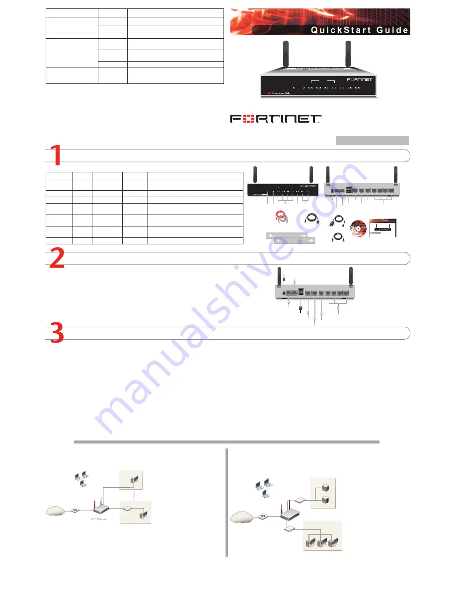
Checking the Package Contents
Connecting
Planning the Configuration
INTERNAL
DMZ
4
3
2
1
LINK 100
LINK 100
LINK 100
LINK 100
LINK 100
LINK 100
LINK 100
WAN1
WAN2
PWR
WLAN
Ethernet Cables:
Orange - Crossover
Grey - Straight-through
Power Cable
Power Supply
INTERNAL
DMZ
4
3
2
1
LINK 100
LINK 100
LINK 100
LINK 100
LINK 100
LINK 100
LINK 100
WAN1
WAN2
PWR
WLAN
Power
LED
WLAN
LED
WAN 1,2
Interface
DMZ
Interface
Internal
Interface
Front
Internal Interface,
switch connectors
1,2,3,4
Back
1
2
3
4
USB
WAN2
WAN1
DMZ
DC+12V
Internal
Power
Connection
USB
WAN2
DMZ
WAN1
RJ-45 Serial
Connection
Modem
Connection
(FortiWiFi-60AM)
Modem Console
RJ-45 to
DB-9 Serial Cable
2 Mounting Brackets
Documentation
FortiWiFi-60A/AM
Copyright 2006 Fortinet Incorporated. All rights reserved.
Trademarks
Products mentioned in this document are trademarks.
Q u i c k S t a r t G u i d e
INTERNAL
DMZ
4
3
2
1
LINK 100
LINK 100
LINK 100
LINK 100
LINK 100
LINK 100
LINK 100
WAN1
WAN2
PWR
WLAN
1
2
3
4
USB
WAN2
WAN1
DMZ
DC+12V
Internal
Optional connection to DMZ network
Straight-through Ethernet cable connects
to Internet (public switch, router or modem)
Straight-through
Ethernet cables connect
to computers on internal network
Power cable connects to power supply
Optional redundant connection to Internet
Modem connection (FortiWiFi-60AM)
Optional connection to a serial modem
(FortiWiFi-60A)
Modem Console
Optional RJ-45 to DB-9 serial cable
connects to management computer
Connector
Type
Speed
Protocol
Description
Internal
RJ-45
10/100 Base-T Ethernet
4-port switch connection to up to four devices or the
internal network.
WLAN
Antenna
802.11 a/b/g Wireless connections to LAN.
WAN1 and 2 RJ-45
10/100 Base-T Ethernet
Redundant connections to the Internet.
DMZ
RJ-45
10/100 Base-T Ethernet
Optional connection to a DMZ network or to other
FortiWiFi-60A/AM units for high availability (HA).
CONSOLE
RJ-45
9600 bps
RS-232
serial
Optional connection to the management computer.
Provides access to the command line interface (CLI).
USB
USB
USB
Optional connection for FortiUSB key for firmware
backup and installation.
Phone cable
RJ-11
Phone line for internal modem.
Place the unit on a stable surface. It requires 1.5 inches (3.75 cm) clearance above and
on each side to allow for cooling.
Locate the FortiWiFi-60 in a prominent location within a room for maximum coverage,
rather than in a corner.
Be aware of the construction of your environment, concrete and metal walls can hamper
signal strength.
Keep the AP and wireless devices at least 10 feet away from appliances such as micro-
wave ovens and cordless phones.
•
•
•
•
Connect the FortiWiFi unit to a power outlet and to the internal and external networks.
Before beginning to configure the FortiWiFi unit, you need to plan how to integrate the unit into your network. Your configuration plan is dependent upon the operating mode that you select:
NAT/Route mode (the default) or Transparent mode.
NAT/Route mode
In NAT/Route mode, each FortiWiFi unit is visible to the network that it is connected to. All of
its interfaces are on different subnets. Each interface that is connected to a network must be
configured with an IP address
that is valid for that network.
You would typically use NAT/
Route mode when the FortiWiFi
unit is deployed as a gateway
between private and public net-
works. In its default NAT/Route
mode configuration, the unit
functions as a firewall. Firewall
policies control communications
through the FortiWiFi unit. No
traffic can pass through the
FortiWiFi unit until you add fire
-
wall policies.
In NAT/Route mode, firewall policies can operate in NAT mode or in Route mode. In NAT
mode, the FortiWiFi unit performs network address translation before IP packets are sent to
the destination network. In Route mode, no translation takes place.
Transparent mode
In Transparent mode, the FortiWiFi unit is invisible to the network. All of its interfaces are on
the same subnet. You only have to configure a management IP address so that you can make
configuration changes.
You would typically use the For
-
tiWiFi unit in Transparent mode
on a private network behind
an existing firewall or behind a
router. In its default Transpar-
ent mode configuration, the unit
functions as a firewall. No traffic
can pass through the FortiWiFi
unit until you add firewall poli
-
cies.
You can connect up to four net
-
work segments to the FortiWiFi
unit to control traffic between
these network segments.
Refer to the Documentation CD-ROM for information on how to control traffic, and how to configure HA, antivirus protection, FortiGuard, Web content filtering, Spam filtering,
intrusion prevention (IPS), and virtual private networking (VPN).
FortiWiFi-60A / AM
01-30004-0287-20070517
Quick configuration using the default settings
You can quickly set up your FortiWiFi unit for a home or small office using the web-based
manager and the default settings in NAT/Route mode.
All you need to do is set your network computers to use DHCP, access the web-based
manager, and configure the required settings for the WAN1 interface. You can also configure
DNS and a default route if needed. The FortiWiFi unit automatically assigns IP addresses to
up to 100 computers in the internal network.
Connect the FortiWiFi unit to the network.
Set the all the network computers to use DHCP to automatically obtain an IP address.
The FortiGate internal interface acts as a DHCP server for the internal network and assigns
IP addresses to all computers in the range 192.168.1.110 –192.168.1.210.
From the management computer browse to https://192.168.1.99. The FortiGate web-
based manager appears.
Go to
System
>
Network
>
Interface
and select Edit for the WAN1 interface.
1.
2.
3.
4.
Select one of the following Addressing modes
Manual: enter a static IP address and netmask, select OK, and go to step 6
DHCP: to get an IP address from the ISP select DHCP and go to step 9
PPPoE: to get an IP address from the ISP select PPPoE and go to step 9
Go to
System
>
Network
>
DNS
.
Select one of the following DNS settings
Obtain DNS server address automatically: select to get the DNS addresses from the
ISP, select Apply
Use the following DNS server addresses: select and enter the DNS server address
-
es given to you by the ISP, select Apply
Go to
Router
>
Static
, select Create New, enter the default gateway address and select
OK. Network configuration is complete. Proceed to part 7 of this
Quick Start Guid
e.
Select Retrieve default gateway from server and Override internal DNS options if your
ISP supports them, select OK, and proceed to part 7 of this
Quick Start Guide
.
Go to step 6 if you are not selecting these options.
5.
•
•
•
6.
7.
•
•
8.
9.
LED
State
Description
Power
Green
The FortiGate unit is on.
Off
The fortiGate unit is off.
WLAN
Green
Traffic on WLAN link.
Link
(Internal, DMZ, WAN1,
WAN2)
Green
The correct cable is in use and the connected equip-
ment has power.
Flashing
Green
Network activity at this interface.
Off
No link established.
100
(Internal, DMZ, WAN1,
WAN2)
Green
The interface is connected at 100 Mbps.
Internet
Router
Internal
network
DMZ
10.10.10.1
10.10.10.2
Internal Network
192.168.1.3
Internal
192.168.1.99
Wireless
users
Routing policies controlling
traffic between internal
networks.
WAN1
204.23.1.5
NAT mode policies controlling
traffic between internal
and external networks.
Internet
Router
DMZ network
Web Server
Mail Server
Internal
network
Hub or switch
DMZ
WAN1
Internal
Wireless
users


