

© Copyright 2006 Fortinet Incorporated. All rights reserved.
Products mentioned in this document are trademarks or registered trade-
marks of their respective holders.
Regulatory Compliance
FCC Class A Part 15 CSA/CUS
21 December 2006
FortiMail Unit LED Indicators
Light Icon
Description
ID
FortiMail system ID.
!
System status. This light is on when a system or hardware is running
properly. The light blinks when a non-critical condition occurs.
Power indicator.
Hard disk activity. The light flashes when the FortiMail unit accesses the
hard disk.
Checking the Package Contents
Connecting
Planning the Configuration
1
CONSOLE
2
3
4
Power Cable
Rack-Mount Brackets
Ethernet Cables:
Orange - Crossover
Grey - Straight-through
Front
Back
Power
RJ-45 to
DB-9 Serial Cable
Power (backup)
1
CONSOLE
2
3
4
Documentation
FortiMail-2000
Copyright 2006 Fortinet Incorporated. All rights reserved.
Trademarks
Products mentioned in this document are trademarks.
Q u i c k S t a r t G u i d e
Ethernet
Connections
RJ-45
Serial
Connection
USB ports
for future use
1
CONSOLE
2
3
4
1
CONSOLE
2
3
4
Power cable connects
to power outlet
Backup
power outlet
Straight-through Ethernet cable connects
to hub or switch on the network
RJ-45 to DB-9 serial cable connects
to management computer
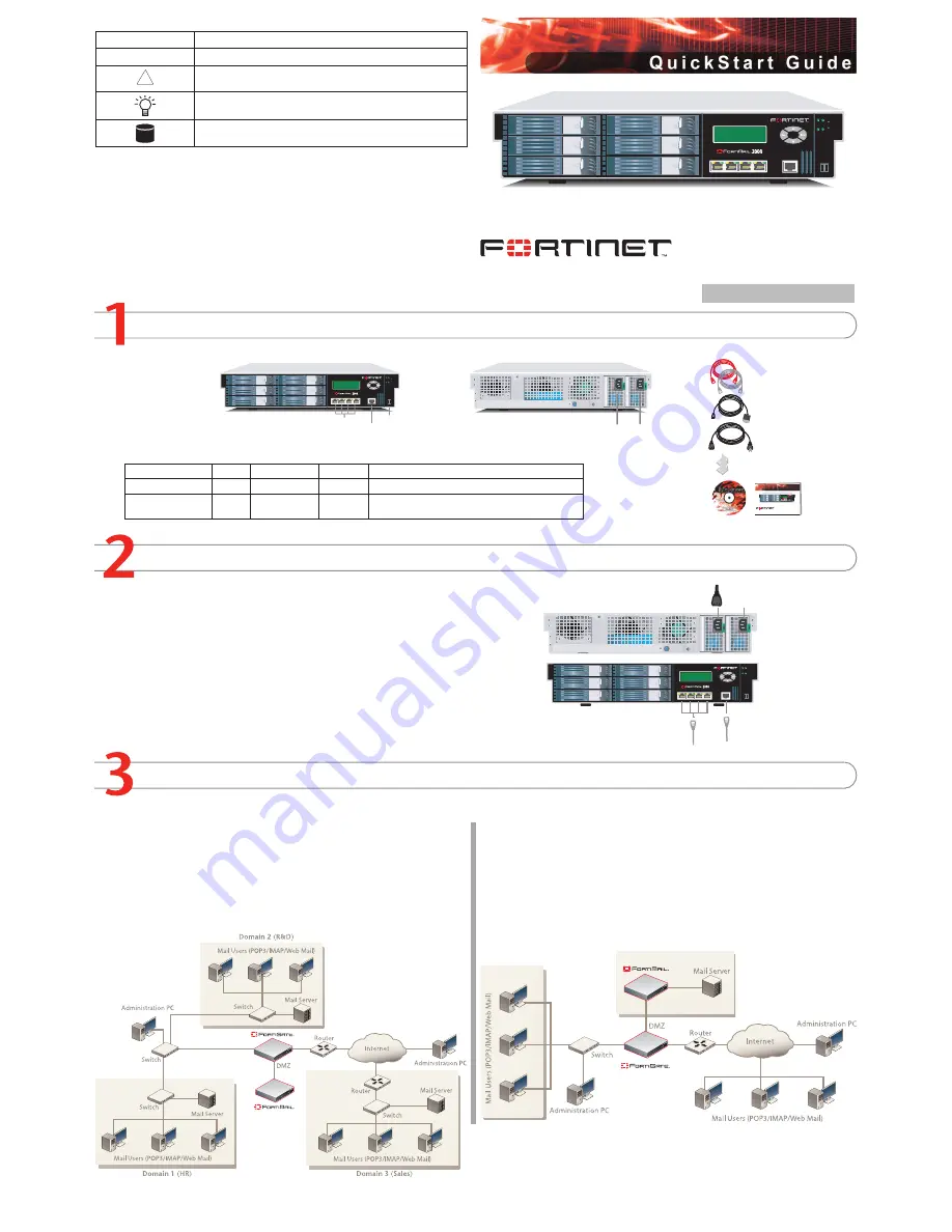
Gateway mode
In Gateway mode, the FortiMail unit protects your email server by scanning the SMTP traffic
for viruses and spam messages as it passes through the FortiMail unit.
You can configure your firewall or DNS server to ensure that incoming SMTP traffic goes
through the FortiMail unit before reaching the email server. Optionally, you can configure the
email server to use the FortiMail unit as the relay server for outgoing SMTP traffic.
The FortiMail unit integrates into your existing network with only minor changes to your
network configuration.
Transparent mode
In Transparent mode, the FortiMail unit protects your email server by scanning the SMTP traf-
fic for viruses and spam messages as it passes through the FortiMail unit.
The FortiMail unit provides seamless integration into existing networks. You can place the
FortiMail unit in front of the existing email server without any configuration changes to the
existing network topology, for filtering email messages. This means that all of the FortiMail
interfaces are on the same IP subnet and appears to other devices as a bridge. Alternatively,
you can configure the FortiMail unit as a combination of a bridge and a router by assigning
IP addresses to some of its interfaces. In this situation, the interfaces can be on different
subnets.
FortiMail-2000
06-28000-0322-20061221
Place the FortiMail unit on a stable surface or mount it in a 19-inch rack. It requires 1.5
inches (3.75 cm) clearance on each side to allow for cooling.
Make sure the power is not plugged into the wall before connecting the power cable and
turning on the unit.
The Status light flashes while the unit is starting up and remains lit when the system is up
and running.
•
•
•
Connect the FortiMail unit to a power outlet and to the network hub or switch.
Server mode
In Server mode, the FortiMail unit provides basic email server functionality, supporting
WebMail, SMTP, POP3 and IMAP email protocols. In addition, the FortiMail Server provides
antivirus, antispam, email archiving, logging and reporting services.
Connector
Type
Speed
Protocol
Description
Ports 1, 2, 3, 4
RJ-45
10/100Base-T Ethernet
Connection to the network
CONSOLE
RJ-45
9600 bps
RS-232
Connection to the management computer. Provides
access to the command line interface (CLI).


