FOR-A MV-410RGB, Operation Manual
The FOR-A MV-410RGB is a high-quality video switcher offering exceptional performance and versatility. Its Operation Manual is available for free download on manualshive.com, providing users with a comprehensive guide to maximize functionality. Explore the immense potential of this cutting-edge product with our comprehensive manual, accessible with just a click.
Share
Download


Reviews:
No comments
Related manuals for MV-410RGB

VG Series
Brand: H3C Pages: 4

TM-WIFI440-Z
Brand: TempAlert Pages: 22

MultiConnect Conduit
Brand: Multitech Pages: 37

fatbox G3
Brand: AMPLIFIED ENGINEERING Pages: 20

460PBSDFM-N70PB
Brand: RTA Pages: 73

GHP Reactor Steer-by-Wire Volvo
Brand: Garmin Pages: 6

get magic
Brand: Tele System Pages: 16

IM 689-2
Brand: McQuay Pages: 52

ENTRYPROX
Brand: HID Pages: 38

769301
Brand: Televes Pages: 46

MD-N32
Brand: Rosslare Pages: 19

SC10E4IM Series
Brand: San Telequip Pages: 65

ePAQ-9100
Brand: QEI Pages: 47

2701HGV-B
Brand: 2Wire Pages: 2

MiniHub Pro WLRRTES-102 TBMH110
Brand: Browan Pages: 14

Armadillo-IoT Gateway G3
Brand: Atmark Pages: 129
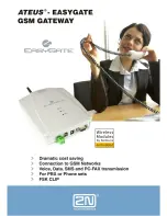
Ateus-EasyGate
Brand: 2N Pages: 35

AIK050
Brand: IFM Electronic Pages: 33


