

FA9520-SETUPGUIDE-E-1.DOCX
FA-9520
Quick Setup Guide
1
POWER
switch
Pressing the "
|
" side turns on the power.
2
FS1/LOCK
button
Used to select FS1. Press and hold down to lock the front panel
operation. Press and hold down again to unlock. In the FA-9520 mode,
locks only the operation for FS1.
3
FS2/LOCK
button
Used to select FS2. In the FA-9520 mode, locks the front panel
operation for FS2 when pressed and held down. Press and hold this
button down again to unlock.
4 EVENT button Used to save and load events.
5
Status
indicator
VIDEO IN
green
Input signal
present in
FS1/FS2
REMOTE
green
CONTROL
SETTING is set to
REMOTE
Unlit
No input
signal in
FS1/FS2
Unlit
CONTROL
SETTING is set to
LOCAL
AUDIO IN
green
Assigned
audio signal
present
DC
POWER
Red
Power failure
Unlit
No
assigned
audio signal
Unlit
Normal power
supply
GENLOCK
green
Genlock
signal
present
FAN
ALARM
Red
Fan failure
Unlit
No genlock
signal input
Unlit All fans normal
6 Menu display Used to display menus and make operational settings
7
Controls
(F1-F4) UNITY
buttons
Used to change operational settings. Turn and select values.
The Unity buttons return the settings to the default values.
8 Arrow buttons
Single-arrow
Used to move between parameters. (lights if
accessible)
Double-arrow
Used to move between menus. (lights if accessible)
9 Menu buttons Used to select menus.
Make sure that the FS1/LOCK and FS2/LOCK button LEDs are lit green or unlit before
starting an operation. If FS1/LOCK and/or FS2/LOCK button LED(s) are lit orange, all
operations on the front panel for FS1 and/or FS2 except the LOCK button(s) are
disabled. Press and hold the FS1/LOCK and/or FS2/LOCK button(s) that are lit orange to
unlock the operations.
* Complete connections before turning the power of the unit on.
https://www.for-a.com/
You can download manuals and other documents by registering your email address.
The FA-9520 has 2 operational modes; FA-9500 mode, in
which the unit operates/functions almost the same as the
former FA-9500, and FA-9520 mode with 2 independently
operational frame synchronizers. This quick setup guide mainly
describes operation in FA-9520 mode. To change the mode,
see Operation Manual section 7-2.
“MU OPERATION”.
Packing list: FA-9520 (1), Quick Setup Guide (1) CD (including
Operation Manuals), AC cord (1), AC cord retaining clip (1 set),
Rack mount bracket set (1 set)
Option items: FA-95RU, FA-95PS (with AC cord, AC cord retaining
clip (1 set), FA-10DCCRU, FA-95DACBL (installed before
shipment), FA-95D-D, FA-95DE-E, FA-95AIO (with PC-3307-1
cable), FA-95ALA, Software option: FA-95CO
1. Rear Connectors
AC Power connector 1
A
C
10
0 -
24
0V
5
0/6
0 H
z I
N
1
FAN2
S
E
R
.
N
O
.
LAN2
LAN1
REMOTE
DIGITAL AUDIO IN / OUT
7 / 8
5 / 6
3 / 4
1 / 2
ANALOG AUDIO
GENLOCK IN
COMPOSITE
OUT2
OUT1
IN
B
OUT4
OUT3
IN2
OUT2
OUT1
SDI
IN1
A
FAN1
AC
10
0 -
24
0V
5
0/6
0 H
z I
N2
HD/SD-SDI input connector 1
HD/SD-SDI output connector 1, 2
HD/SD-SDI input connector 2
HD/SD-SDI output connector 3, 4
Analog composite input connector Analog composite output connector
Genlock input connector
Ground terminal
Ethernet port (for future use)
Ethernet port
Digital audio input/output connector
FAN1
SLOT A SLOT B
Analog audio Input/output connector *1
Remote control connector*2
FAN2
AC Power connector 2
*1 Refer to the Operation Manual section 12.
“Analog Audio Connection” for details on the
Analog audio connector.
*2 Refer to the Operation Manual section 14.
“REMOTE” for details on the Remote control
connector.
◆
FA-95DACBL option
Digital audio output connectors
3/4
5/6
1/2
7/8
FAN2
3/4
7/8
FAN1
5/6
B
A
COMPOSITE
1/2
LAN2
SDI
REMOTE
LAN1
COMPOSITE
OUT3
OUT2
IN1
SDI
ANALOG AUDIO
LAN2
DIGITAL AUDIO IN/OUT
OUT4
OUT1
IN2
OUT1
OUT2
IN
A
C
1
0
0
-2
4
0
V
5
0
/6
0
H
z
IN
2
DIGITAL AUDIO OUT
S
E
R
.N
O
.
GENLOCK IN
AC
10
0-2
40
V 5
0/6
0H
z IN
1
Digital audio input/output connectors
(Will be input connectors when the FA-95DACBL is installed.)
Reference signal input connector
◆
FA-95D-D/DE-E option
OUT
IN
REF IN
Dolby E
Digital audio input connector Digital audio output connector
ANALOG COMPONENT I/O
◆
FA-95AIO option
Analog component input/output connector
(
use with the
supplied PC-3307-1 cable.)
Refer to sec. 16. FA-95AIO Option for details on connectors.
2. Installing the AC Cord Retaining Clip
After connecting the AC cord, secure the AC cord with the supplied ladder strap/retaining
clip assembly to prevent accidental removal from the FA-9520. Be sure to install the AC
cord retaining clip before mounting the unit into a rack.
1) Wrap the retaining clip around the AC cord. (with the anchor of the ladder strap toward
the unit.)
2) Insert the anchor into the hole next to the AC IN socket.
3) Lightly fasten the clip around the AC cord.
4) Plug in the power cord.
5) Slide the clip on the ladder strap toward the plug.
6) Fasten the clip tightly.
7) Gently pull on the AC cord to ensure it is secured.
3. Front Operation Panel
POWER
ON
OFF
PS1/LOCK
PS2/LOCK
EVENT
VIDEO IN
GENLOCL
REMOTE
AUDIO IN
FAN ALARM
DC POWER
F 1
F 2
F 3
F 4
F A - 9 5 2 0
H D / S D F R A M E S Y N C H R O N I Z E R
DISPLAY
F 1
UN ITY
F 2
UN ITY
UN ITY
F 3
F 4
UN ITY
PROCESS
SDI AUDIO
MAPPING
VIDEO OP
AUDIO OP
C C
A V O
CLIP
DELAY
VIDEO S YS
AUDIO S YS
AE S AUDIO
CONV1
ANALOG
IN SEL
DOWNMIX
ST AT US
OT HER
CONV2
MAST ER
OUT SEL
M O D E
VIDEO
AUDIO
2)
4)
3)
5)
6)
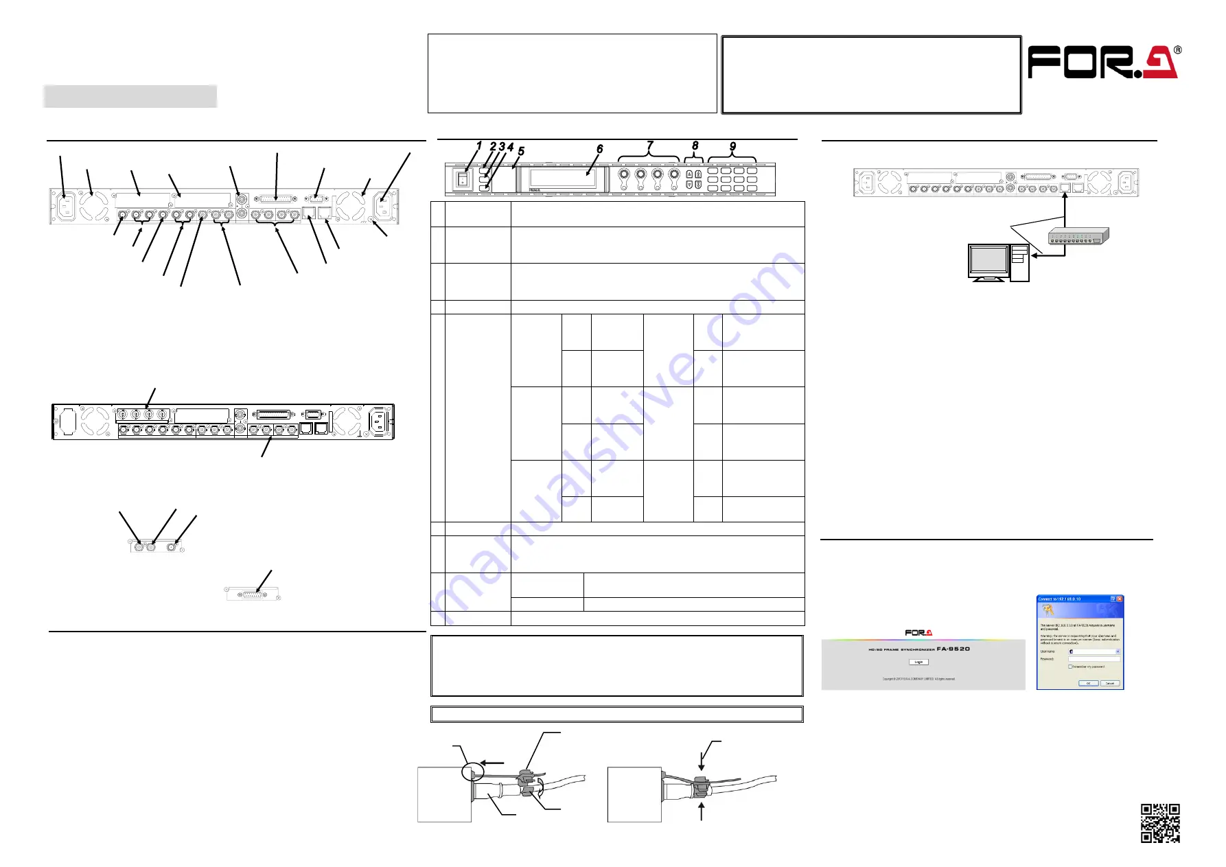
4. Connecting a Computer
Direct connection using a crossover LAN cable is also possible.
◆
Connection using a hub
AC
10
0 -
24
0V
5
0/6
0 H
z I
N 1
FAN2
S
E
R
.
N
O
.
LAN2
LAN1
REMOTE
DIGITAL AUDIO IN / OUT
7 / 8
5 / 6
3 / 4
1 / 2
ANALOG AUDIO
GENLOCK IN
COMPOSITE
OUT2
OUT1
IN
B
OUT4
OUT3
IN2
OUT2
OUT1
SDI
IN1
A
FAN1
AC
10
0 -
24
0V
5
0/6
0 H
z I
N2
Straight-through
LAN cable
PC
LAN1
The FA-9520 network settings must be adjusted for your network after
purchase.
・
The FA-9520
’s LAN1 IP address is set to 192.168.0.10 at the factory.
・
Set the IP address and subnet mask of the computer as follows:
IP address:
192.168.0.1 to 192.168.0.254 (except 192.168.0.10)
Subnet mask:
255.255.255.0
In Windows, open the
Local Area Connection Properties
dialog box, and
open the
Internet Protocol (TCP/IP) Properties
window. The network settings
must be made in the window. See the user
’s manual of your computer for
details.
See section 9-8
“Network Settings” for details on changing the FA-9520’s IP
address.
The FA-9520
’s IP address can be checked in the NETWORK INFO menu
(menu page 197). To go to the NETWORK INFO menu, press the
STATUS/OTHER button, then a single-arrow button.
5. Connecting via a WEB Browser
Open a web browser on your computer, and enter the address as
http://192.168.0.10/ (factory default setting) in the address bar.
Press the [Enter] key to connect to the FA-9520.
The login page is displayed.
Click
Login
.
The authentication dialog appears.
Enter your user name and password. (The default user name and password are
set at the factory.)
User name
: fa9520
Password
: foranetwork
See section 9.
“Control via WEB Browser” for details on Web browser control
screens.


