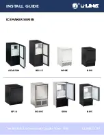
background image

MCC425A/W_S
MCE425A/W_S
ER425A/W

MCC425A/W_T
MCE425A/W_T
MFC425A/W_T
MFE425A/W_T

CP425A/W
EP425A/W

01083856R01

801 Church Lane • Easton, PA 18040, USA
Toll free (877) 612-5086 • +1 (610) 252-7301
www.follettice.com

Operation and Service Manual 

MC_425A/W, MF_425A/W, _P425A/W 

Ice Machines - 230 V 50 Hz, 220 V 60 Hz

Following installation, please forward this manual 

to the appropriate operations person.

Summary of Contents for CP425A/W

Page 1: ...425A W 01083856R01 801 Church Lane Easton PA 18040 USA Toll free 877 612 5086 1 610 252 7301 www follettice com Operation and Service Manual MC_425A W MF_425A W _P425A W Ice Machines 230 V 50 Hz 220 V 60 Hz Following installation please forward this manual to the appropriate operations person ...

Page 2: ...2 MC_425A W MM_425A W MF_425A W _P425A W Ice Machines ...

Page 3: ...nufacturer its service agent or similarly qualified persons in order to avoid a hazard Connect to potable water supply only This appliance can be used by children aged 8 years and above and persons with reduced physical sensory or mental capabilities or lack of experience and knowledge if they have been given supervision or instruction concerning use of the appliance in a safe way and understand t...

Page 4: ...cal system 12 Technical specifications all models 14 Electrical control system schematic 230 V 50 Hz 16 Electrical control system schematic 220 V 60 Hz 17 Electrical control system operation 17 Refrigeration system all models 27 Replacement parts 30 Replacement ice machine ordering matrix 30 Air cooled skins assembly MCE425A_S 31 Water cooled skins assembly MCE425W_S 32 Louvered docking station MC...

Page 5: ...anation of the problem Before you begin After uncrating and removing all packing material inspect the equipment for concealed shipping damage If damage is found notify the shipper immediately and contact Follett LLC so that we can help in the filing of a claim if necessary Check your paperwork to determine which model you have Follett model numbers are designed to provide information about the typ...

Page 6: ...prevent back flow do NOT connect drains Follett recommends a Follett water filter system be installed in the ice machine inlet water line standard capacity 00130229 high capacity 00978957 carbonless high capacity 01050442 Ambient Air temperature 100 F 38 C max 50 F 10 C min best performance below 80 F 27 C Water temperature 90 F 32 C max 45 F 10 C min best performance below 70 F 21 C Water pressur...

Page 7: ...88 48 cm 18 88 48 cm 2 32 5 9 cm 4 40 11 2 cm 15 22 38 7 cm 11 03 28 0 cm 8 03 20 4 cm 5 03 12 8 cm 2 34 6 cm Dimensions and clearances Entire front of ice machine must be clear of obstructions connections to allow removal 12 30 5 cm clearance above ice machine for service 6 15 3 cm minimum clearance between exhaust side of ice machine and any adjacent equipment MCE425A ER425A 18 45 7 cm minimum 1...

Page 8: ...nsibility to see that this cleaning is performed according to the schedule below Service problems resulting from lack of preventive maintenance will not be covered under the Follett warranty Symphony Plus Frequency Drain Line weekly Drain Pan Drip Pan weekly Exterior as needed Condenser monthly air cooled only Ice Machine semi annually Transport Tube semi annually Ice machine must be sanitized pri...

Page 9: ...drain Wait for the LOW WATER light to turn on 5 Remove lid from cleaning cup and fill about 1 quart until SafeCLEAN Plus solution completely fills the reservoir Place lid back on cup 6 CLEANER FULL light will turn on and machine will start cleaning and sanitizing cycle then rinse three times this process takes approximately 15 minutes 7 When machine is finished cleaning and sanitizing the MAINTENA...

Page 10: ...e water supply when the ice machine is not running When the ice machine is running a layer of ice forms on the interior surface of the evaporator This ice is continuously removed by a slowly rotating 10 RPM auger The auger carries the ice upward into the cavity formed by the top bearing housing and the compression loop where it is compressed to remove excess water When the ice reaches the desired ...

Page 11: ... until the Normal Low sensor is exposed triggering the water feed solenoid on Water will fill until the Normal High sensor is activated Note The potable water dissolved solids content must be greater than 10 ppm for the water control system to function properly If using reverse osmosis water filtration system ensure T D S level is greater than 10 ppm Fig 1 Water system diagram CLEANING CUP WATER S...

Page 12: ... initiating the time delay period When the time delay expires the machine will restart provided that the LOW BIN light is on DIP Switch Settings Sleep cycle dispense duration OFF ON 1 2 3 4 5 6 7 8 4 5 4 5 4 5 4 5 35 s 15 s 5 s 60 s OFF POSITION ON POSITION Sleep cycle enabled Not used Sleep cycle dispense duration 60 min time delay Flush enabled Maint timer OFF OFF ON Sleep cycle disabled Not use...

Page 13: ... the water be shut off to a running machine a soft error will occur The error sequence is as follows During operation the water level falls to the normal low sensor and when it does the water feed solenoid is energized If water is not detected at the normal low sensor within 10 seconds a soft error will occur The machine will shut down and TIME DELAY and LOW WATER LEDs will be lit After time delay...

Page 14: ...0 F 32 2 C 100 F 37 8 C 220 V 230 V 220 V 230 V 220 V 230 V 220 V 230 V 220 V 230 V Amperage 2 65 2 25 2 77 2 36 2 89 2 46 3 01 2 57 3 13 2 68 High side pressure psi 219 199 256 233 293 266 330 306 367 346 Low side pressure psi 28 29 30 31 33 33 35 36 38 38 Water cooled Condenser water temperature 60 F 15 6 C 70 F 21 1 C 80 F 26 7 C 90 F 32 2 C 100 F 37 8 C 220 V 230 V 220 V 230 V 220 V 230 V 220 ...

Page 15: ...375 345 315 285 lbs 27 184 170 156 142 129 kg 90 395 365 335 305 275 lbs 32 179 166 152 138 125 kg Water Cooled ice machine capacity 24hrs 220 V 60 Hz Condenser Water Temperature F C Inlet Water Temperature F C F 60 70 80 90 100 C 16 21 27 32 38 50 454 442 431 419 408 lbs 10 206 200 195 190 185 kg 60 435 421 407 394 380 lbs 16 197 191 185 179 172 kg 70 416 400 384 368 351 lbs 21 187 181 174 167 15...

Page 16: ...ROWN 14 BLACK 122 BLUE 07 BLACK 51 WHITE 52 COMP R C S O L C2 START 1 2 3 4 5 6 7 8 9 GREEN 53 COMPRESSOR COMPRESSOR ELECTRICAL BOX BLACK 51 WHITE 52 GREEN 53 RED 54 ORANGE 55 BLACK 56 GREEN 57 BLACK 58 BLACK 59 6 4 1 2 5 BLACK 61 WHITE 62 GREEN 63 WHITE 64 BLACK 65 BLACK 66 GREEN 67 BLACK 68 BLACK 69 C1 RUN BLACK 66 BLACK 69 BLACK 71 15 04 05 WHITE DRAIN CLOG SENSOR BLACK VIOLET DRAIN CLOG MODEL ...

Page 17: ... BLUE BLUE BROWN VIOLET GRN YEL COMPRESSOR VIOLET BLACK GRN YEL GRAY S C R THERMAL O L P14 HI PRS ICE AUX CURRENT SENS P17 WATER LEVELS P10 SERIAL COMM JUNCTION BOX START RELAY GROUND TERMINALS ON MOUNTING PLATE Electrical control system operation The wiring diagrams that follow illustrate the circuitry of these Follett ice machines used with ice dispensers Both normal operation of the ice machine...

Page 18: ...P6 P21 P20 P19 P3 P22 P4 AUGER WATER LEVELS BIN P11 HI PRS L1 R S C RED WHITE WHITE BLACK BROWN BLUE RED BLACK YELLOW Compressor Electrical Box COMPRESSOR 1 2 3 4 5 6 7 8 BLACK N P15 I c e D i s p e n s e I n p u t Normal operation Stage 1 220 V 60 Hz The 220 V 60 Hz is identical to the 230 V 50 Hz EXCEPT that the compressor output and neutral are reversed as shown in the diagram below The remaini...

Page 19: ...ACK BROWN BLUE RED BLACK YELLOW Compressor Electrical Box COMPRESSOR 1 2 3 4 5 6 7 8 BLACK N P15 I c e D i s p e n s e I n p u t Normal operation Stage 3 After the initial high current draw drops off the gearmotor start relay contacts open dropping out the start winding The condenser fan output P3 comes on 0 5 seconds later 5 2 1 Start Run Compressor T O L MAINTENANCE LOW WATER TIME DELAY SLEEP CY...

Page 20: ...D i s p e n s e I n p u t Normal operation Stage 5 As the compressor comes up to normal running speed its start winding generates a voltage potential across the relay s coil This energizes the coil to open the contact and drop out the start capacitor The ice machine is now in a normal ice making mode The ice machine will produce ice until the bin level control in the ice dispenser is satisfied 5 2...

Page 21: ...s p e n s e I n p u t Normal operation Stage 7 The fan motor continues for 10 minutes before shutting off The TIME DELAY LED remains on for 20 minutes The ice machine will not start while the TIME DELAY LED is on To restart the ice machine for troubleshooting purposes depress the reset button to clear the control board 5 2 1 Start Run Compressor T O L MAINTENANCE LOW WATER TIME DELAY SLEEP CYCLE M...

Page 22: ...Switch Drain Clog Sensor P6 P21 P20 P19 P3 P22 P4 AUGER WATER LEVELS BIN P11 HI PRS L1 R S C RED WHITE WHITE BLACK BROWN BLUE RED BLACK YELLOW Compressor Electrical Box COMPRESSOR 1 2 3 4 5 6 7 8 BLACK N P15 I c e D i s p e n s e I n p u t Quiet Night Sleep cycle The board monitors ice dispensing through a line voltage input to P15 If the ice dispense has not be initiated for more than 5 seconds d...

Page 23: ...N P15 I c e D i s p e n s e I n p u t Diagnostic Stages High gearmotor amps Stage 1 The HI AMPS error and TIME DELAY LEDs are on indicating that the control board has sensed an over torque condition at the P4 terminal more than 1 8A from the gearmotor or no current draw 0A and shut the ice machine down strike one The HI AMPS and TIME DELAY LEDs will remain on for 60 minutes after an over torque co...

Page 24: ...D i s p e n s e I n p u t High gearmotor amps Stage 3 If a second occurrence happens during the 60 minute monitoring period the HI AMPS LED will come on again and shut the machine down strike two The HI AMPS LED wihout the TIME DELAY LED will indicate to the technician that two consecutive over torque situations have occurred The ice machine is shut down at this time and locked out It will not res...

Page 25: ...efore restarting LOW WATER LED will remain ON until the water level is satisfied 5 2 1 Start Run Compressor T O L MAINTENANCE LOW WATER TIME DELAY SLEEP CYCLE MAKING ICE LOW BIN POWER SERVICE HI AMPS HI PRESSURE DRAIN CLOG CLEANER FULL High Pressure Switch R S C Gearmotor Start Relay Start Relay N L1 Fan A B C D Water Sensors RESET Fill Valve Drain Valve 3 4 2 Bin T Stat Clean Switch Drain Clog Se...

Page 26: ... 4 2 Bin T Stat Clean Switch Drain Clog Sensor P6 P21 P20 P19 P3 P22 P4 AUGER WATER LEVELS BIN P11 HI PRS L1 R S C RED WHITE WHITE BLACK BROWN BLUE RED BLACK YELLOW Compressor Electrical Box COMPRESSOR 1 2 3 4 5 6 7 8 BLACK N P15 I c e D i s p e n s e I n p u t Drain clog If continuity is seen between the two drain clog sensor probes the DRAIN CLOG LED will come on and the machine will shut down T...

Page 27: ...refrigerants Improper refrigeration servicing procedures will void the factory warranty Evacuation Evacuate the system to a level of 500 microns When the 500 micron level is reached close valves and both manifold and shut down the vacuum pump Allow the system to sit for approximately 20 minutes During this period the system pressure should not rise If the system pressure rises and stabilizes there...

Page 28: ...ve 10 Remove ice compression loop located at top of auger 11 Lift auger straight up and out of evaporator 12 Remove nut and lower vee band coupling from bottom of evaporator 13 Lift evaporator to clear bottom bearing assembly 14 Loosen hex head bolt in side of mounting base with 5 16 wrench and lift lower bearing assembly 15 Remove condensate shield 16 Remove 4 Allen head machine screws holding mo...

Page 29: ...stall upper bearing and seal assembly rotating bearing to slip pin into auger slot 13 Install upper vee band clamp and nut to 70 in lb 14 Install evaporator insulation 15 Install compression nozzle and tubing 16 Secure ice transport tube with clamp Fig 6 1 Note Clamp must be oriented as shown in order for the insulation to be placed properly 17 Install compression nozzle insulation Fig 6 2 18 Inst...

Page 30: ...fill drop in bin MC_425AJS MC_425AJS MC_425WJS MC_425WJS Flake ice machine on top of bin MFE425ABT MFE425ABT MFE425WBT MFE425WBT Dispensers with integral ice machines C E25CI425A 230 V C EP425A C E50CI425A 230 V C EP425W MicroChewblet ice machine on top of bin MM_425ABT MM_425ABT MM_425WBT MM_425WBT MicroChewblet ice machine RIDE fill bin MM_425ABS MM_425ABS MM_425WBS MM_425WBS MicroChewblet ice m...

Page 31: ...se 01068220 5 Panel right side 01068238 6 Panel left side and rear 1 piece 01068246 7 Bushing 01026152 8 Panel top 01068253 9 Tube drain 01016948 10 Fitting water 01065375 11 Fitting drain 00109728 Not shown Power cord 01111673 Not shown Tubing ice transport per foot 01148642 Not shown Insulation ice tube per foot 501176 MC_425A W MM_425A W MF_425A W _P425A W Ice Machines 31 ...

Page 32: ...00195966 2 Fitting water 01065375 3 Fitting drain 00109728 4 Panel front 01068261 5 Spacer base 01068220 6 Panel right side 01068238 7 Tube drain 01016948 8 Panel left side and rear 1 piece 01068246 9 Bushing 01026152 10 Panel top 01068253 Not shown Power cord 01111673 Not shown Tubing ice transport per foot 01148642 Not shown Insulation ice tube per foot 501176 ...

Page 33: ... _P425A W Ice Machines 33 Louvered docking station MCE425A W_T 1 2 3 4 Reference Description Part 1 Louver front 01006154 2 Cover front 01068279 3 Tube drain 01055185 4 Lovered docking station 01068287 Not shown Power cord 01111673 ...

Page 34: ... W MM_425A W MF_425A W _P425A W Ice Machines Evaporator FOOD SERVICE HEALTHCARE FLAKER COMPONENTS 26 17 24 1 3 4 5 19 7 6 8 10 11 12 16 9 21 20 13 1 FLAKER 18 25 23 2 27 22 3 4 MicroChewblet 29 28 17 18 17 15 18 ...

Page 35: ...02832 Not shown Mounting base gearbox 01067693 15 Compression nozzle with single drain 01064674 16 Drain pan evaporator 00181990 17 Tube compression nozzle vent 01148691 18 Tube compression nozzle single drain 01148675 Not shown Grease Chevron SRI 2 14 oz 501111 19 Insulation jacket evaporator 01049592 20 Relay gearmotor 00120055 21 Cover black plastic 01012228 22 Nozzle compression dual drain 010...

Page 36: ...36 MC_425A W MM_425A W MF_425A W _P425A W Ice Machines Air cooled ice machines 230 V 50 Hz 2 15 21 7 6 10 22 3 20 17 16 9 13 1 14 8 18 19 5 11 23 25 4 24 12 26 ...

Page 37: ...foot 01148774 13 Fan blade 500474 14 Motor fan 230 V 50 Hz and 220 V 60 Hz 00149765 15 Bracket fan motor 01067107 Not shown Overload compressor 230 V 50 Hz 01087188 16 Compressor 230 V 50 Hz 01111665 17 Tube fill purge reservoir solenoid evaporator feed 01051192 Not shown Water inlet fitting brass 01065275 Not shown Fitting reservoir plastic 1 4 stem x 1 4 push in 00121699 18 Jacket insulation TXV...

Page 38: ...38 MC_425A W MM_425A W MF_425A W _P425A W Ice Machines Air cooled ice machines 220 V 60 Hz 2 21 3 20 17 13 14 19 5 12 26 4 10 6 8 11 16 15 1 9 18 23 25 7 22 24 ...

Page 39: ...5 per foot 01148774 13 Fan blade 500474 14 Motor fan 230 V 50 Hz and 220 V 60 Hz 00149765 15 Bracket fan motor 01067107 16 Compressor 220 V 60 Hz internal overload 01148527 17 Tube fill purge reservoir solenoid evaporator feed 01051192 Not shown Water inlet fitting brass 01065275 Not shown Fitting reservoir plastic 1 4 stem x 1 4 push in 00121699 18 Jacket insulation TXV 502830 19 Bracket ice tube...

Page 40: ...40 MC_425A W MM_425A W MF_425A W _P425A W Ice Machines Water cooled ice machines 230 V 50 Hz 18 2 3 17 19 20 4 10 8 5 9 21 12 13 6 11 16 16 15 7 1 22 23 25 26 24 14 ...

Page 41: ...2 10 Mounting bracket gearbox 01067693 11 Bracket electrical box mounting 01068139 Not shown Overload compressor 230 V 50 Hz 01087188 12 Compressor 230 V 50 Hz 01111665 13 Coil condenser 00195933 14 Tube clean 21 5 per foot 01148774 Not shown Water inlet fitting brass 01065275 15 High pressure cutout 502732 16 Ty rap 2 required 204584 17 Tube fill purge reservoir solenoid evaporator feed 01051192 ...

Page 42: ...42 MC_425A W MM_425A W MF_425A W _P425A W Ice Machines Water cooled ice machines 220 V 60 Hz 18 2 3 17 19 20 4 10 8 5 9 12 13 6 11 16 16 15 1 22 23 25 26 24 14 21 7 ...

Page 43: ... 502832 10 Mounting bracket gearbox 01067693 11 Bracket electrical box mounting 01068139 12 Compressor 220 V 60 Hz internal overload 01148527 13 Coil condenser 00195933 14 Tube clean 21 5 per foot 01148774 Not shown Water inlet fitting brass 01065275 15 High pressure cutout 502732 16 Ty rap 2 required 204584 17 Tube fill purge reservoir solenoid evaporator feed 01051192 18 Bracket ice tube entry 0...

Page 44: ... Hz 01087154 3 Board control circuit 230 V 50 Hz and 220 V 60 Hz 01111657 4 Switch clean 00117036 5 Stand offs board 8 required 00903005 6 Box electrical start run components 220 V 60 Hz 01148535 Not shown Bin thermostat MCE425A WBT MCE425A WHT MFE425A WBT and MFE425A WHT only 500514 Not shown Relay bin signal power to contact closure 01020734 Not shown Jumper bin signal 01069095 Not shown Power c...

Page 45: ...e filter carton of 12 00954305 Carbonless high capacity filter system Not shown Carbonless high capacity water filter system one per ice machine Horizon and MaestroPlus series ice machines 01050442 Not shown Carbonless high capacity water filter cartridge primary single 01050426 Not shown Carbonless high capacity water filter cartridge primary carton of 6 01050434 Not shown Water pre filter cartri...

Page 46: ...evará un momento realizar hoy mismo el registro En el formulario incluimos un espacio en blanco para sus comentarios y opiniones Infórmenos sobre su experiencia para que podamos incorporarla a nuestros continuos esfuerzos de mejora Nos enorgullecemos de producir un equipo excepcional y trabajamos duro para respaldarlo con un soporte técnico y un servicio de atención al cliente de primera Le rogamo...

Page 47: ...Fazemos votos de que o nosso equipamento cumpra ou exceda as suas expectativas dado que temos por objetivo fornecer produtos e serviços de elevado valor que mereçam a sua total satisfação Pedimos lhe que leia o manual de instalação e operações em anexo É importante que a instalação seja levada a cabo de acordo com as especificações da fábrica para que o seu equipamento funcione com a eficiência má...

Page 48: ...allationen genomförs enligt fabrikens anvisningar så att din utrustning arbetar med högsta effektivitet Follett LLC ansvarar inte för följdskador kostnader avgifter eller förluster som orsakats av fel på maskinen Fullständiga garantivillkor finns på vår hemsida www follettice com productwarranties Garantiregistrering och utvärdering av utrustning är viktig för oss så att vi kan följa upp vär ultru...

Reviews: