FlyTech POS 112 SERIES, User Manual
The FlyTech POS 112 SERIES User Manual is a comprehensive guide designed to help you maximize the functionality and features of your FlyTech POS system. With easy-to-follow instructions and detailed illustrations, this free manual provides step-by-step guidance for setup, troubleshooting, and optimally utilizing your device. Download it now for free at manualshive.com.
Share
Download


Reviews:
No comments
Related manuals for POS 112 SERIES

T-5801MH
Brand: Farenheit Pages: 4
BC-200
Brand: Baby Control Digital Pages: 12

65 Series
Brand: Daktronics Pages: 29
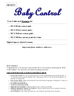
Baby Control BC-439
Brand: Hama Pages: 20

d10
Brand: Racegeek Pages: 3

ZL 7261 CL-5
Brand: Vision Pages: 3

TW191D
Brand: I-Inc Pages: 19

G08 Series
Brand: Vector Pages: 42

B17DF
Brand: Hansol Pages: 25

LCM-15V5
Brand: Westinghouse Pages: 15
ProPixel PSX-5901-125MN-3
Brand: Daktronics Pages: 5

EH-24
Brand: AG Neovo Pages: 32

TDS-32F Series
Brand: Touch Revolution Pages: 21

YS-MBE01
Brand: Yasun Pages: 19

Baby Care 10 Eco Zero
Brand: AUDIOLINE Pages: 32

DP900
Brand: Newall Pages: 49

L26W56SA and
Brand: Zenith Pages: 64

CCTV-1TEST
Brand: Monacor Pages: 18


