Fluke 574, User Manual
The Viatran 574 Installation Data Manual is a comprehensive resource designed to assist users with easy and efficient installation of the Viatran 574 product. This manual can be conveniently downloaded for free from our website, providing step-by-step instructions and crucial information for seamless product installation.
Share
Download


Reviews:
No comments
Related manuals for 574
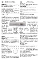
SC 25
Brand: Vega Technologies Pages: 2

ALFA 51 PI
Brand: VDH Pages: 4

E 4 G
Brand: Lauda Pages: 119

AX-ET-6
Brand: Axio Pages: 4

Modulo
Brand: SPC Pages: 18

DD01*
Brand: Amana Pages: 8

dt-705
Brand: LifeSource Pages: 4

103818
Brand: haupa Pages: 11

GFX50
Brand: GeneralAire Pages: 12

Always Perfect
Brand: Brookstone Pages: 11

Grill Alert
Brand: Brookstone Pages: 17

PT3
Brand: iHealth Pages: 20

DET-306b
Brand: JOYTECH Pages: 10

502A
Brand: CHY Pages: 3

eti RAYTEMP 8
Brand: YaliTech Pages: 4

CTE–5101
Brand: KMC Controls Pages: 4

CTC-4001
Brand: KMC Controls Pages: 2

IR-CA series
Brand: Chino Pages: 36


