FLIR E-EST Series, User Manual
The FLIR E-EST Series user manual is available for free download from manualshive.com. This comprehensive manual provides detailed instructions on how to use and optimize your FLIR E-EST Series product. Download the manual today to enhance your experience with this innovative thermal imaging solution.
Share
Download


Reviews:
No comments
Related manuals for E-EST Series

camera
Brand: 21PRO Pages: 54
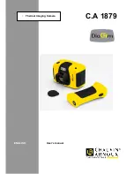
C.A 1879
Brand: Chauvin Arnoux Pages: 22

MiVue 358
Brand: Navman Pages: 8

XS10 Extreme Edition
Brand: Polaroid Pages: 1

TC3231
Brand: Megger Pages: 20

CDR 900
Brand: Cobra Pages: 13

DVR-C310R
Brand: Alpine Pages: 39

Ccd2000
Brand: Kenwood Pages: 44

VREC-130RS
Brand: Pioneer Pages: 240

VREC-170RS
Brand: Pioneer Pages: 259

CAMVI-0360-A
Brand: MONSTER VISION Pages: 30

HTG
Brand: HEADQUARTERS Pages: 56

TRACE IR 25 Series
Brand: ICI Pages: 11

A4000-E1
Brand: HX Pages: 35

PhotoMaker X4
Brand: Kaiser Baas Pages: 26

AR-MI50
Brand: Mi-Witness Pages: 46

M08
Brand: Azdome Pages: 32

Road Safety Guard 351.136
Brand: Tronios Pages: 16


