


INSTALLATION AND
OPERATION MANUAL
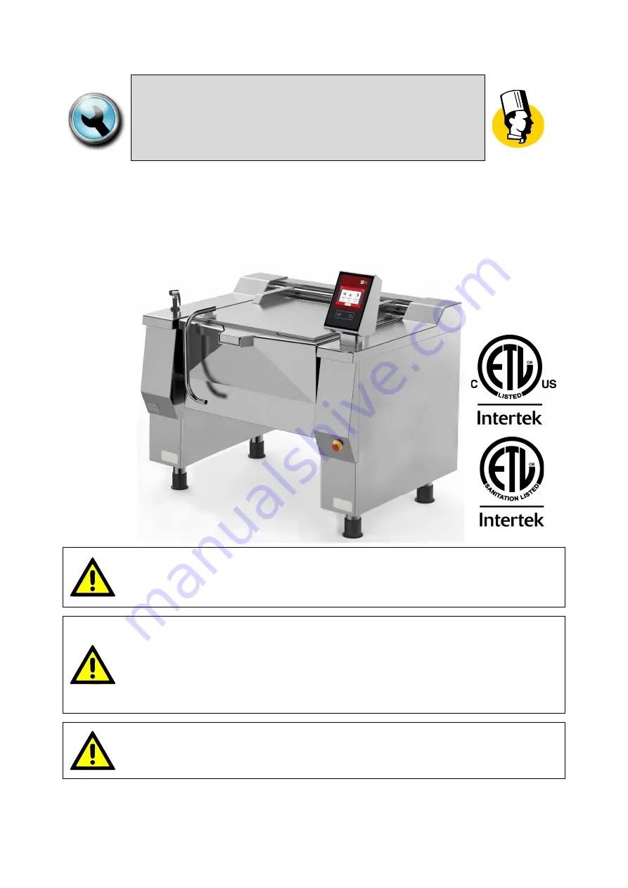
“BETTERPAN”
RECTANGULAR BRATT PANS, GAS TYPE
MODD. UDBRG…_V1 ; UDBRG…-C_V1
FOR YOUR SAFETY:
Do not store or use gasoline or any other flammable liquids and
vapours in the vicinity of this or any other appliance.
WARNING:
Improper installation, operation, adjustment, alteration, service or
maintenance can cause property damage, injury or death.
Read the installation, operating and maintenance instructions
thoroughly before installing, operating or servicing this equipment.
PURCHASER: Instructions to be followed in the event that the operator
of this appliance smells gas must be posted in a prominent location.
This information shall be obtained by consulting the local gas supplier.


