


T170 ML2016 Rev. A
9281 LeSaint Drive • Fairfield, Ohio 45014
Phone (513) 874-2818 • Fax (513) 874-2914
Sales: 1-800-543-7166
Activate
Activate
Your Warranty
Your Warranty
By Registering
By Registering
TODAY!!!
TODAY!!!
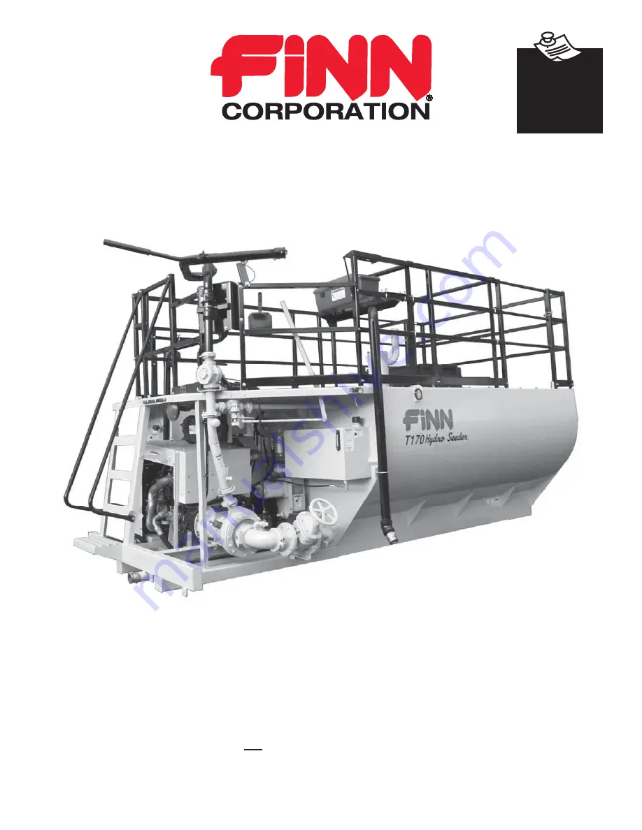
T170 HydroSeeder
®
Operator Instructions and Parts Manual
Model
ML
Serial No. _____________


