VTUG-PT-L
Festo AG & Co. KG
Postfach
73726 Esslingen
Germany
+49 711 347-0
www.festo.com
Brief description
8031867
1402NH
[8031869]
Original: de
Valve terminal type VTUG-PT-L
1
Range of application and certifications
The VTUG valve terminal with interlock (type VTUG-PT-L) is used exclusively for
control of pneumatic actuators within the limits of the technical data and is inten-
ded for installation in machines and automation systems.
The VTUG-PT-L is intended for use in an industrial environment.
The target group of this description consists of trained specialists in control and
automation technology who have experience with the installation of valve terminals.
Warning
Danger of injury through uncontrolled movements of connected equipment.
Make sure that electrical and pneumatic equipment are in a de-energised and
pressureless status.
Before working on the pneumatics:
• Switch off the compressed air supply
• Vent the valve terminal
Before working on the electrical components, e.g. before installation or mainten-
ance work:
• Switch off the power supply
In this way, you can avoid:
– uncontrolled movements of loose tubing
– accidental and uncontrolled movements of the connected actuators
– undefined switching states of the electronics
– functional damage.
Note
Installation and commissioning should only be carried out by qualified personnel
in accordance with this brief description. Commission a valve terminal only if it
has been completely mounted and wired! Employ the valve terminal VTUG-PT-L
only in conformity with protection class IP40.
Note
IO-Link® and TORX® are registered trademarks of the respective trademark
owners in certain countries.
Note
Certain configurations of the product have been certified by Underwriters Labor-
atories Inc. (UL) for the USA and Canada (
Title).
If the UL requirements are to be complied with in your application, please ob-
serve the regulations of the separate UL-specific special documentation. The
relevant technical data listed there also apply here.
2
Pilot air supply for pilot control
The VTUG valve terminal is configured for operation with internal or external pilot
air depending on your order.
Internal pilot air supply
The pilot pressure is branched from duct 1 for internal pilot air supply. If your VTUG
valve terminal is configured for internal pilot air supply, the ports 14 in the mani-
fold rail are sealed with blanking plugs.
External pilot air supply
The pilot pressure is supplied via port 14 for external pilot air supply. If your VTUG
valve terminal is configured for external pilot air supply, a special blanking screw is
fitted in the manifold rail (
Fig. 1). Conversion of the pilot air variant is described
in the assembly instructions VABM-L1-...GR.
3
Pressure zones
Using separators, the valve terminal VTUG-… can be divided into pressure zones.
Mounting of these separators is described in the assembly instructions VABD-... B.
4
H-rail mounting
The VTUG-PT-L valve terminal is designed for mounting on an H-rail.
Note
If the VTUG-PT-L is subjected to vibration or shock loads, H-rail mounting is not
permissible.
H-rail mounting is described in the assembly instructions VAME-T-M4.
5
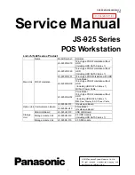
Display and connecting elements of the electronics
The following electrical connection and display components can be found on the
VTUG-PT-L:
5
2
1
3
4
1
Interlock Sub-D plug connector
2
Status-LED X1, I-port communica-
tion
3
I-port/IO-Link connection (plug,
5-pin, M12, A-coded)
4
Thread for earthing screw for con-
nection to functional earth
(
chap. 7)
5
Special blanking screw for external
pilot air supply
Fig. 1
5.1 LED display X1
The subsequent table shows the statuses and significance for the LED X1:
LED
display
Status and significance
LED illuminated green:
– normal operating status
LED flashing green:
– data communication is not satisfactory
LED flashing alternately green/red:
– 24 V load voltage supply not satisfactory (no voltage, undervoltage or short
circuit)
LED flashing red:
– device errors
LED illuminated red:
– no data communication and
– 24 V load voltage supply not satisfactory (no voltage, undervoltage or short
circuit)
LED dark:
– no operating voltage
Fig. 2