Feig Electronic OBID i-scan ID ISC.LR200 Series, Manual
The Feig Electronic OBID i-scan ID ISC.LR200 Series is a cutting-edge RFID reader offering unparalleled accuracy and reliability. With advanced features and user-friendly interface, this product ensures seamless integration into any system. Download the free manual for the ISC.LR200 Series from our website for detailed instructions on setup and usage.
Share
Download


Reviews:
No comments
Related manuals for OBID i-scan ID ISC.LR200 Series
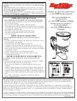
3100
Brand: EarthWay Pages: 2

CQDP383U - AUTO RADIO/CD DECK
Brand: Panasonic Pages: 15

CQRX400U - AUTO RADIO/CD/MP3 DECK
Brand: Panasonic Pages: 44

1210 Series
Brand: JARLTECH Pages: 31

Wearable Ring Scanner
Brand: M3 Mobile Pages: 35

CT2214
Brand: Neilsen Pages: 20

PCIe-1600
Brand: Titan Electronics Pages: 16

DS1100-1 Series
Brand: Datalogic Pages: 48

WDT1000-P
Brand: ICS Advent Pages: 34

SWDAB2
Brand: Streetwize Pages: 5

SCANNDY
Brand: Panmobil Pages: 34

7644882010
Brand: Blaupunkt Pages: 21

CR950
Brand: Code Pages: 16

FASTETHERNET 6U
Brand: Sun Microsystems Pages: 106

KBM-XP67
Brand: KoamTac Pages: 31

Creader V II+
Brand: Launch Pages: 20

TE200 Series
Brand: Digium Pages: 73

RONDINI SQFT
Brand: Tar River Pages: 22


