background image

MLED-CTRL Box 

User manual 


August 2020 - Version EN 1.1 

www.fdstiming.com


1.


Presentation  


1.1.


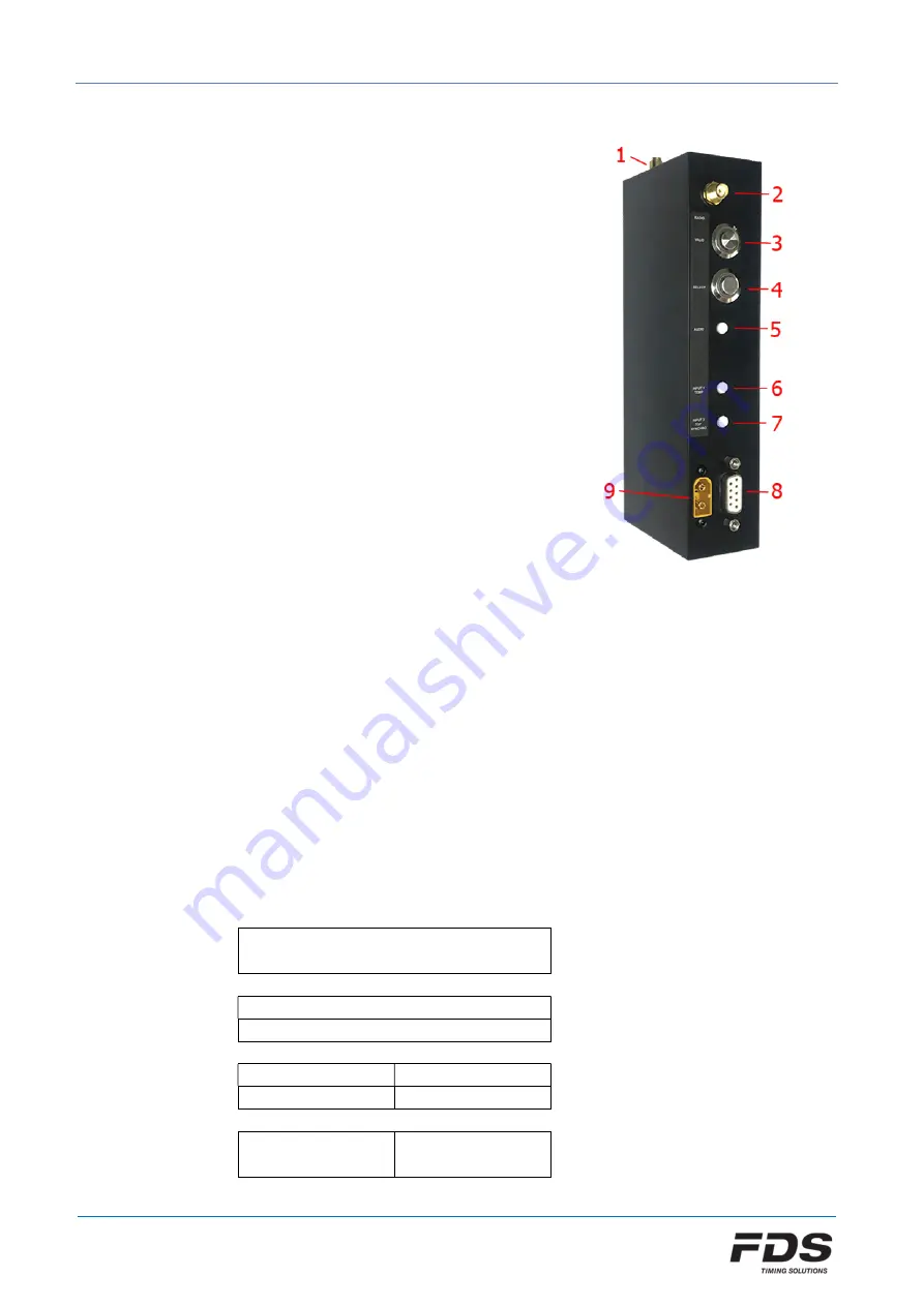
Switches and connectors 


1) Active GPS antenna (SMA connector) 
2) Radio antenna 868Mhz-915Mhz (SMA connector) 
3) Validation switch (Orange) 
4) Selection switch (Green) 
5) Audio out 
6) Input 1 / temperature sensor 
7) Input 2 / Sync Output 
8) RS232 / RS485 
9) Power connector (12V-24V) 


1.2.


MLED assembly 


The most common configuration comprises of 3 or 4 x MLED panels adjoined to form a 
display fully configurable to either a single full height line of characters or multiple lines as 
below. Another configuration proposed is 2 rows of 6 modules which form a 192x32cm 
display area. 
The total display area is divided into 9 zones (A – I) as the schematic below. Be aware that 
some zones share the same display area and should not be used together. A line number as 
well as a color can be assigned to each zone via the IOS or PC setup application.  
It is recommended to assign the value “0” to any unused zone. 
The MLED-CTRL box must always be connected to the lower right MLED module. 


Summary of Contents for MLED-CTRL Box

Page 1: ...nels adjoined to form a display fully configurable to either a single full height line of characters or multiple lines as below Another configuration proposed is 2 rows of 6 modules which form a 192x3...

Page 2: ...S or PC setup application The first two modes are part of the basic firmware Modes 3 6 belong to a 1st optional group and require an activation key to operate Mode 7 belongs to a 2nd optional group wh...

Page 3: ...on jack input 1 or wirelessly via WIRC 1 the running time starts On receiving an impulse on jack input 2 or wirelessly via WIRC 2 the time taken is displayed b No sequenced mode Any Inputs Starts and...

Page 4: ...impulse on jack input 2 or wirelessly via WIRC 2 finish time is recorded Speed is then calculated using the time difference and distance and displayed b No sequenced mode Any Inputs Start and Finish...

Page 5: ...s mode works either with the external Jack inputs 1 2 or with WIRC signals Jack input 1 or WIRC 1 is used to start stop the countdown Jack input 2 or WIRC 2 to reset it to its initial value All parame...

Page 6: ...cording to the selected layout all other relevant parameters should be configured Before countdown After initial power up the display enters a wait for synchro state The default synchro is defined in...

Page 7: ...s set according to the sectors definition Every second a light is turned on until zero is reached E Cnt 2 Lights Full size countdown value is displayed max 4 digits as well as 1 traffic light on each...

Page 8: ...cles time interval Time between each countdown cycle This value must be equal or greater than the countdown value plus the end of countdown time Countdown value Countdown time in seconds Countdown col...

Page 9: ...al settings EXT INPUTS Parameters of the 2 external inputs Jack connectors RADIO Radio settings and WIRC wireless photocell pairing EXIT Leave the menu General Settings DISP INTENSITY Change the defau...

Page 10: ...SETTINGS PRINT RESULTS EXIT Leave the menu Mode Settings Speed Mode DISTANCE Set the distance DISTANCE UNITS Select the distance unit meters or feet SPEED UNITS Select the speed unit Km h Mph m s or K...

Page 11: ...chro GPS or manual EXIT Leave the menu CntDown Param Start Clock Mode COUNTDOWN VALUE Countdown value COUNTDOWN COLOR Initial countdown color SECTOR 1 TIME Start time of color sector 1 SECTOR 1 COLOR...

Page 12: ...ur setup Apps Important Do not use a same WIRC WINP on a Display and a TBox simultaneously 4 1 Factory settings Factory settings can be restored by pressing both Menu Buttons on MLED CTRL during power...

Page 13: ...together 5 3 Input_1 Temperature sensor Input This 3 5mm jack connector combines 2 functionalities 1 Time capture input 1 2 Digital temperature sensor input 1 External input 1 2 Temperature Sensor Da...

Page 14: ...S232 RS485 Any standard RS232 DSUB 9 cable can be used to drive the MLED Ctrl from a computer or other compatible device On the connector 2 pins are reserved for RS485 connection DSUB 9 female pinout...

Page 15: ...bits no parity 1 stop bit Baud Rate 9600bds 6 2 Characters Set All standard ASCII characters 32 126 excepted for the char which is used as delimiter 0123456789 ABCDEFGHIJKLMNOPQRSTUVWXYZ _ abcdefghijk...

Page 16: ...or overlay between two characters position permanent cp cmd s first character position 1 32 e last character position 1 32 c color code Example STX 13 cp 1 10 2 cp 11 16 3 LF Characters position 1 to...

Page 17: ...lay The rest of the display is not modified Fill all display Command Description fi c Fill with a defined colour the full display area Only 50 of the LEDs are turned on to reduce current and heating f...

Page 18: ...S232 d Run the program FdsFirmwareUpdate e Select the COM Port f Select the update file bin g Press Start on the program h Connect the power cable to MLED CTRL Box MLED module firmware can also be upd...

Page 19: ...or discrepancies between this manual and the product described The sale of products services of goods governed under this publication are covered by FDS s standard Terms and Conditions of Sales and t...

Reviews: