OPERATION, MAINTENANCE AND
SPARE PARTS MANUAL
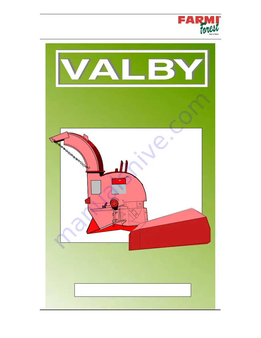
CH 140 CHIPPER
I--USA--291102--JaK
www.farmiforest.fi
03513950
03514400
FARMI Forest
Ahmolantie 6
FIN---74510 PELTOSALMI
FINLAND
Tel. +358 (0) 17 83 241
Fax +358 (0) 17 823 606
It is very important to read this instruction
handbook thoroughly before using the machine!
CHIPPER CH 140
From machine: 351 1200