


web:
www.farmet.cz
e-mail: [email protected]
IČ: 46504931
DIČ: CZ46504931
Farmet a. s.
Jiřinková 276
552 03 Česká Skalice, CZ
telefon: +420 491 450 111
fax:
+420 491 450 136
GSM:
+420 774 715 738
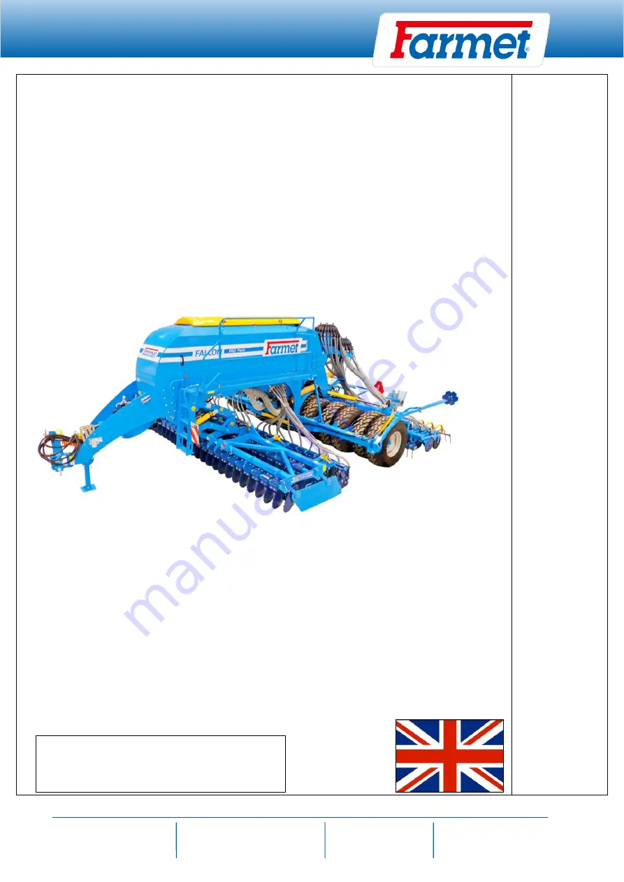
OPERATING INSTRUCTION
Falcon PRO
OPERAT
ING IN
STRU
CTIONS
SN:2021/0123
VIN:
FALCON COMPACT
Edition : 8 / validity from 27.09.2021


