


TLP 700MV • Setup Guide
Overview
The Extron TLP 700MV is a wall-mounted TouchLink
®
Panel that provides simple and versatile configuration and control for a range of
IP Link
®
control systems.
Graphic and text objects are displayed on the screen. These objects have system control functions associated with them and the
touch overlay allows you to activate or regulate those functions.
The TLP 700MV communicates with the configurable IP Link controller through an Ethernet connection to an IP Link device. Two BNC
connectors allow the screen to be used to preview composite video or S-video.
NOTE:
The RJ-45 output on the rear panel of the TLP 700MV must be connected to a network switch, hub, or router that is
connected to an Ethernet LAN or the Internet. An Extron IP Link controller must also be connected to the same network.
Suggested models include IPL T S series (for example, IPL T S4), IPL 250, IPL T CR 48, or IPL T SFI 244.
This guide provides basic instructions for experienced installers to mount and perform initial configuration on the TLP 700MV. Full
instructions and reference material can be found in the
TLP 700MV and TLP 700TV User Guide
, which is available on the Extron
website (
TLP 700MV Front Panel Features
LIGHTS
ON
DISPLAY
MUTE
AUDIO
MUTE
SPEECH
MUTE
AUTO
IMAGE
FREEZE
LIGHTS
OFF
SCREEN
SCREEN
HELP
?
4
4
4
5
5
5
6
6
6
1
1
1
2
2
2
3
3
3
LIGHTS
ON
DISPLAY
MUTE
AUDIO
MUTE
SPEECH
MUTE
AUTO
IMAGE
FREEZE
LIGHTS
OFF
SCREEN
SCREEN
HELP
?
7
7
7
8
8
8
9
9
9
¢
¢
¢
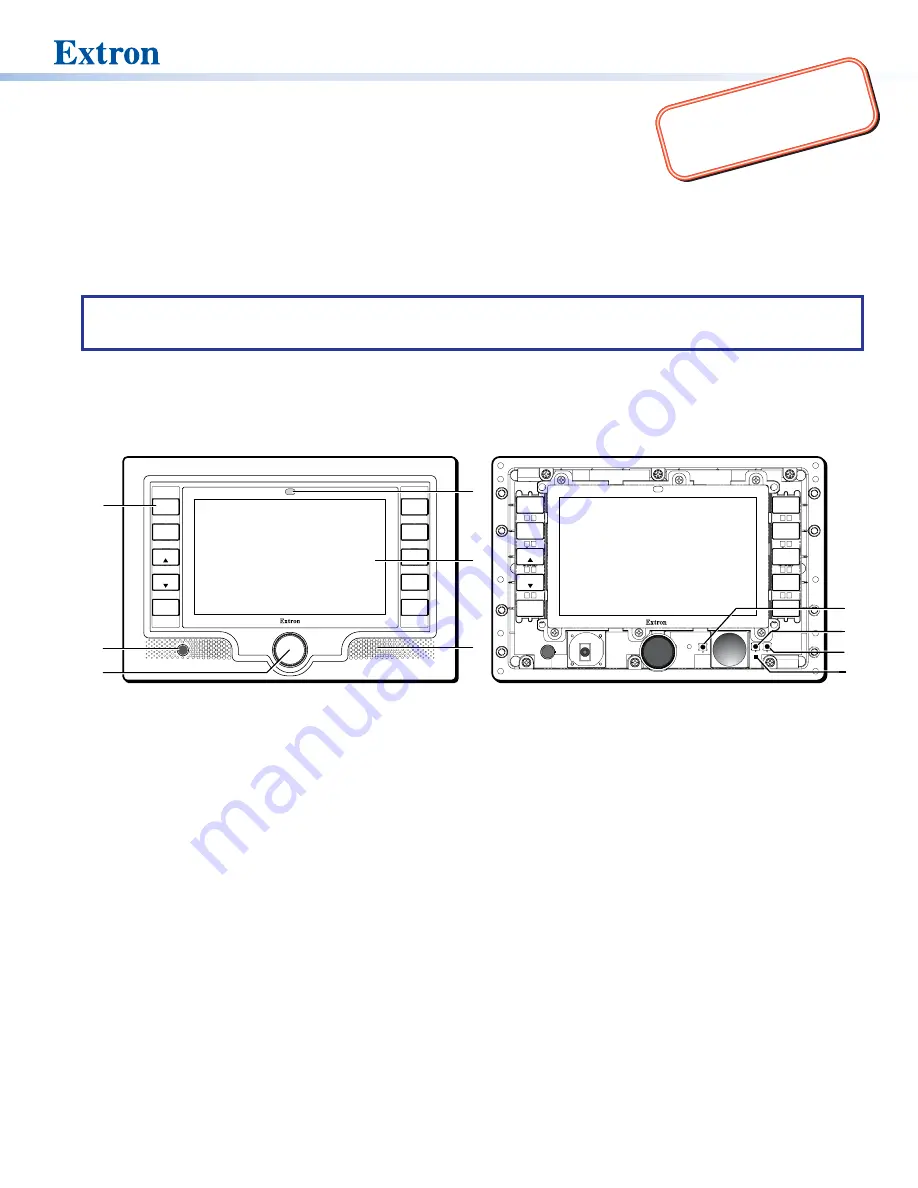
Figure 1.
TLP 700MV Front Panel (left) and Front Panel with Bezel Removed to Show Recessed Buttons (right).
1
Buttons
— These ten backlit push-buttons (five on either side of the screen) can be configured, using the Extron Global
Configurator software, to control commonly used functions.
2
Motion detector
— This detector is capped with a small Fresnel lens that focuses light onto the sensor. When no motion has
been detected for a user-defined period of time, the unit goes into sleep mode. When motion is detected in the vicinity of the
panel, the screen display is restored and all buttons are active.
3
Encoder knob
— This knob is used for volume control.
4
Light sensor
— This sensor monitors the level of ambient light and adjusts the screen brightness and button backlighting.
5
LCD screen
— This 800 x 480 resolution LCD screen has a touch overlay. The Extron GUI Configurator software is used to
design a graphic user interface, which displays buttons, text, or icons on the screen. The Extron Global Configurator software is
used to program these screen objects to perform user-defined functions.
6
Speaker
— A single 2 W speaker provides audible feedback for the user.
7
Reboot button
— This button is recessed behind the bezel. It shuts down and restarts the unit without changing any of the
parameters.
8
Reset button
— This button is recessed behind the bezel and is used to select from the four different reset modes that are
available with TouchLink panels (see
9
Menu button
— This button is recessed behind the bezel. It activates the on-screen menus for setting up the panel and
calibrating the unit.
¢
Reset LED
— This LED is recessed behind the bezel. It is visible only when the faceplate has been removed. It lights as an
indicator for the Reset modes.
1
Product Category
TANT
:
Go to
e
complete user guide and installation
instructions befor
e connecting the
product to the power sou
rce.


