1
IMPO
RTAN
T:
Go to www
.extron.com
for the
complete user guide
, installation
instructions,
and specifications.
12A MAX
POWER OUTPUT 12A MAX
TX
LAN
RX
+5V
INPUT
IR
COM
100-120VAC 50/60Hz
IN
S G
US
LISTED 17TT
AUDIO/VIDEO
APARATUS
®
IPL T PC1
R
100
TX
RX
INPUT
IR
LINK
ACT
POWER
10A MAX
POWER OUTPUT 10A MAX
TX
LAN
RX
+5V
INPUT
IR
COM
200-240V
~ 50/60Hz
IN
S G
US
LISTED 17TT
AUDIO/VIDEO
APARATUS
®
IPL T PC1
R
100
TX
RX
INPUT
IR
LINK
ACT
POWER
SMP 111
STREAMING MEDIA PROCESSOR
INPUT
OUT
HDCP
HDMI
HDMI LINE HDMI
CLIP
AUDIO
CONFIG
USB STORAGE
ALARM
MARK
Rx
Tx
G
RS-232
CONTROL
RESET
+12V
1.0A MAX
INPUTS
OUTPUT
REMOTE
SMP 111
100-240V 0.7A
50-60 Hz
LAN
USB STORAGE
HDMI
HDMI
L
AUDIO
LINE
R
USB STORAGE
MARK
RECORD
Extron
StudioStation 100
Streaming Media
Processor
Extron
SMB 212
Two-gang Surface
Mount Box
Extron
RCP 101 EU
Remote Control
Panel
Extron
IPL T PC1
IP Link AC Power and
Device Controller
OR
Extron
IPL T PC1i
IP Link AC Power and
Device Controller
USB Drive
Wireless Microphone System
(not included)
Audio
USB
Power
Power
Crossover
HDMI
Camera & Lights
(not included)
POWER
STANDBY
POWER
STANDBY
1
3
4
5
6
7
8
9
10
7
11
10
2
Extron
StudioStation • Installation Guide
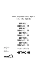
The Extron StudioStation is an easy-to-use single button recording system, which allows users to create recordings with the
touch of a button. The system integrates the StudioStation 100 Streaming Media Processor, a high definition recording and
streaming device, the RCP 101 EU for remote recording controls, the IPL T PC1 for remote AC power, and the SMB 212 to
surface mount the RCP 101 EU. The StudioStation 100 records MP4, M4V and M4A files of full screen HDMI video channel with
mixed audio, and metadata. The StudioStation is ideal for installation beneath conference tables and in lecterns.
The StudioStation turns the power output of the IPL T PC1 (or optional IPL T PCS4) on and off when it is triggered by thumb drive
detection on the RCP 101 EU. When the user inserts a properly formatted USB drive into the RCP 101 EU, the AC power port
of the IPL T PC1 turns on to power up all the attached recording equipment such as the camera, studio lights, and microphone.
Conversely, when the USB thumb drive is removed from the RCP 101 EU, the AC power port of the IPL T PC1 automatically
powers OFF the equipment.
Items included in StudioStation are:
•
1 StudioStation 100
•
1 RCP 101 EU
•
1 Flex55 102
•
(1) 15’ (4.5 m) USB Mini-B to USB type A cable
•
1 IPL T PC1
•
1 SMB 212
•
1 Blank plate
•
(1) 6’ (1.8 m) RJ-45 network crossover cable
NOTES:
•
Throughout this guide, the IPL T PC1 refers to either the IPL T PC1 or IPL T PC1i.
•
For full device configuration and operation details, see the
StudioStation User Guide
at
www.extron.com
or
StudioStation Help File.
Installation Diagram
Figure 1.
Typical StudioStation Application