

If you are ready with the jumper settings for the EX-6410 / EX-6411 , please proceed with
the following installation instructions. Because the designs of computers are different, only
general installation instructions are given. Please refer your computer’s reference manual
whenever in doubt.
1. Turn off the power to your computer and any other connected peripherals.
2. Remove the mounting screws located at the rear and/or sides panels of your Com-
puter and gently slide the cover off.
3. If necessary please install now the external power supply to the card like shown at JP1
& J6 above.
4. Locate an available & correct expansion slot ( see compatibility at technical informa-
tion above) and remove its covers from the rear panel of your computer.
5. Align the EX-6410 / EX-6411 with the expansion slot, and then gently but firmly, insert
the card. Make sure the card is seated and oriented correctly.
6. Then connect the card with a screw to the rear panel of the computer.
7. Gently replace your computer’s cover and the mounting screws.
HARDWARE INSTALLATION
6
5
EX
EX
EX
-
-
-
6410 / EX
6410 / EX
6410 / EX
-
-
-
6411
6411
6411
English
English
English
EX
EX
EX
-
-
-
6410 / EX
6410 / EX
6410 / EX
-
-
-
6411
6411
6411
English
English
English
1
Die EX-6410 / EX-6411 ist eine Firewire 1394B PCI-X Karte. Sie ist mit 3 externen (EX-
6410 Abbildung oben) oder 2 externen und 1 internem Port (EX-6411 Abbildung Seite 4)
ausgestattet. Sie unterstützt den PCI-X Bus mit 64bit und 3,3 Volt. Der serielle PCI-X
Bus unterstützt optimal die Leistung des schnellen Texas Instruments Chips. Die EX-
6410 / EX-6411 gewährleistet so eine sichere Datenübertragung und exzellente Perfor-
mance von bis zu 800Mbit pro Sekunde! Es ist nicht möglich die I/O Adressen und
Interrupts manuell einzustellen, da die Einstellungen der Karte vom System (BIOS) und
beim Installieren des Betriebssystems automatisch vorgenommen werden. Bei der EX-
6410-L handelt es sich um eine LowProfile Karte mit 8cm Bügel für schmale Gehäuse.
BESCHREIBUNG & TECHNISCHE DATEN
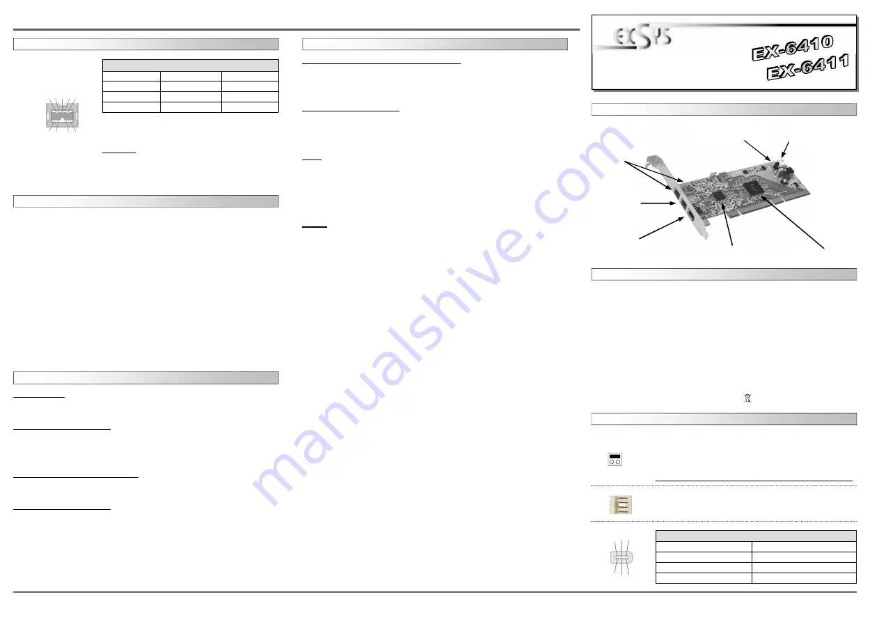
AUFBAU
Kompatibilität:
PCI-X 64Bit 3,3 Volt
Betriebssysteme:
WinME/ 2000/ XP/ Server 20xx/ Vista/ 7/ 8 /MAC/ (Linux vom OS)
Anschlüsse:
2x 9 Pin IEEE1394b Buchse , 1x 6 Pin IEEE1394a Buchse
Lieferumfang:
EX-6410 oder EX-6411, Anleitung
Zertifikate:
CE
CE
CE
CE
/ FCC / RoHS / WEEE DE97424562 / WHQL
Windows Vista/ 7/ 8/ Server 2008 & 2012
The drivers are already integrated in Windows and the EX-6410 / EX-6411 will be in-
stalled automatically.
If you want to use the full performance of the IEEE1394B bus please install Windows
Vista service pack1 it provides the newest IEEE1394B drivers.
CHECK INSTALLED DRIVER
Open the >Device manager< . Now you should see at “IEEE1394 Devices“ the following
new entrys: <Texas Instruments OHCI conform IEEE1394 Hostcontroller>.
If you see this or a similar information the EX-6410 / EX-6411 is installed correctly.
MAC
The drivers are already integrated in MAC OS and the EX-6410 / EX-6411 will be in-
stalled automatically. Only MacOS 8.6 do need a update before the card can be used.
You can download the update on the MacOS homepage (e.g. FireWire Support 2.8.x)
If you want to use the full performance of the IEEE1394B bus please install MacOS X it
is supplied with new IEEE1394B drivers.
In doubt please refer to the installation manual from your MAC OS version !
LINUX
Because each individual distribution and kernel version of Linux is different, sadly we
cant provide a installation instruction here. Please refer to the installation manual for
IEEE1394 ports from your Linux version.
DRIVER INSTALLATION
DRIVER INSTALLATION
Bedienungsanleitung
Bedienungsanleitung
Vers. 2.3 / 13.06.13
JUMPER EINSTELLUNG & ANSCHLÜSSE
Windows ME
The drivers are already integrated in Windows and the EX-6410 / EX-6411 will be in-
stalled automatically.
CHECK INSTALLED DRIVER
Open the >Device manager< . Now you should see at “IEEE1394 Devices“ the following
new entrys: <Texas Instruments OHCI conform IEEE1394 Hostcontroller>.
If you see this or a similar information the EX-6410 / EX-6411 is installed correctly.
Windows 2000/ XP/ Server 2003
The drivers are already integrated in Windows and the EX-6410 / EX-6411 will be in-
stalled automatically.
CHECK INSTALLED DRIVER
Open the >Device manager< . Now you should see at “IEEE1394 Devices“ the following
new entrys: <Texas Instruments OHCI conform IEEE1394 Hostcontroller>.
If you see this or a similar information the EX-6410 / EX-6411 is installed correctly.
JUMPER SETTING & CONNECTORS
PCI = Strom vom PCI-X BUS (Werkseinstellung)
AUX = Strom vom PC-Netzteil des Rechners
(Zur Entlastung des Mainboards und zur stabilen Stromversorgung bei
Verwendung von Endgeräten mit hohem Stromverbrauch).
Anschluss J6 muss dann mit dem PC-Netzteil verbunden werden!
JP1:
PCI
AUX
J6:
Wenn JP1 auf AUX gestellt ist muss J6 mit dem Stromanschluss vom
PC Netzteil verbunden werden! Bitte auf die richtige Polarität achten!
Achtung! Stecker nie bei eingeschaltetem PC ein oder ausstecken!
J4:
1394 6 Pin Firewire Buchse
Pin
Signal
Pin
Signal
1
Power
4
TPB+
2
GND
5
TPA-
3
TPB-
6
TPA+
J1-J3:
IEEE1394 9 Pin port
Pin
Signal
Pin
Signal
Pin
Signal
1
TPB-
4
TPA+
7
SC
2
TPB+
5
TPA (R)
8
POWER
3
TPA-
6
GND
9
TPB (R)
The Port J2 & J3 are shared so you can always only
connect one device at one of the ports
Attention!!!
Please make sure that you connect the cable in the right
order like shown in the list above. If you connect the cable
wrong it can destroy your hardware! The labelling & marks
on the cable must match with the ones on our card.
2 4 6
1 3 5
9 8 7 6 5
1 2 3 4
TI Chipset
J3
1 x Externe 9 Pin
1394B - Buchse
J1 oder J2
1x 1394B 9 Pin
Buchse
(EX-6411) Intern
(EX-6410) Extern
J6
Anschluss für Stecker
vom PC-Netzteil
JP1
Stromquelle wählen
PCI oder AUX
TI Chipset PCI-X Bridge
J4
1 x Externe 6 Pin
1394A - Buchse
1 +5V
2 GND
3 GND
4 +12V


