6
5
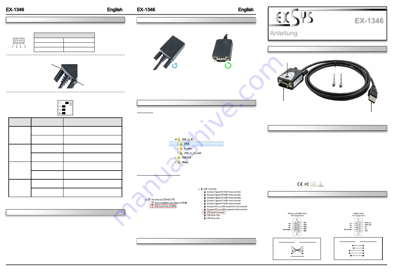
Die EX
-
1346 ist ein Modul zur Umsetzung von USB 2.0 auf eine RS
-
422/485 Schnittstelle mit
FIFO 16C550 Port für den Anschluss von High Speed seriellen RS
-
422/485 Peripherie Geräten
(z.B. Modem, Plotter usw.). Die EX
-
1346 ist mit einem USB 2.0 A
-
Stecker zum Anschluss an
den PC und einem RS
-
422/485 seriellen 9 Pin Stecker ausgestattet. Das USB Modul ist Hot
Plug & Play fähig. Für die Einstellungen der I/O Adressen und Interrupts sind keine Jumper und
Einstellungen notwendig, da die Einstellungen automatisch vom System BIOS und bei der
Installation des Betriebssystems vorgenommen werden.
Kompatibilität:
USB 1.1, 2.0 & 3.2
Betriebssysteme:
Windows 9.x/ ME/ 2000/ XP/ Vista/ 7/ 8.x/ 10/ Server 20xx/ Linux/ MAC
Anschlüsse:
1x USB 2.0 A
-
Stecker, 1x 9 Pin Stecker Seriell RS
-
422/485
Lieferumfang:
EX
-
1346, Adapter 9 Pin Buchse zu 5 Pin Terminal Block,
2x Sechskantmuttern, Treiber CD, Anleitung
Zertifikate:
1
BESCHREIBUNG & TECHNISCHE DATEN
AUFBAU
Anleitung
Vers. 1.0 / 07.09.21
EX
-
1346
ANSCHLÜSSE, STATUS LED
‘
S & DIP
-
SCHALTER
USB 2.0 A
-
Stecker
zum Anschluss an PC
S1:
9 Pin Stecker Seriell RS
-
422/485
2x Sechskantmuttern
DB 9M
RS
-
422/485 Anschlussbelegung:
CONNECTORS, STATUS LED
‘
S & DIP
-
SWITCH
DB9 (EX
-
1346) DB9 (Endgerät)
1 TXD
-
1 TCD
-
2 TXD+ 2 TXD+
3 RXD+ 3 RXD+
4 RXD
-
4 RXD
-
5 GND 5 GND
DB9 (EX
-
1346) DB9 (Endgerät)
1 DATA
-
1 DATA
-
2 DATA+ 2 DATA+
3 NC 3 NC
4 NC 4 NC
5 GND 5 GND
DIP
-
Schalter
HARDWARE
INSTALLATION
Because there are large differences between PC
’
s, we can give you only a general installation
guide for the EX
-
1346. Please refer your computers reference manual whenever in doubt.
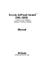
1.
Connect the EX
-
1346 USB to the USB A
-
Port at the your PC.
2.
If you would like to screw the serial cable to the 9 Pin connector of the EX
-
1346, then
unscrew the screws (see Picture 1) and screw the supplied hexagon nuts into the holes on
the EX
-
1346 (see Picture 2). Now you can attach the serial cable to the EX
-
1346.
USB 2.0 A
-
Plug:
USB 2.0 A
-
Plug
Pin
Signal
Pin
Signal
1
VCC
3
DATA+
2
DATA
-
4
GND
Status LED
‘
s:
RXD
TXD
DIP
-
Switch
Position
Description
1
ON (Factory Settings)
2
-
wire RS
-
485 Mode
OFF
4
-
wire RS
-
485 or RS
-
422 Mode
2
ON
Reserved for features in future
OFF (Factory Settings)
Reserved for features in future
3
ON
120 Ohm TXD Termination Resistor is Enabled
OFF (Factory Settings)
120 Ohm TXD Termination Resistor is Disabled
ON
120 Ohm RXD Termination Resistor is Enabled
4
OFF (Factory Settings)
120 Ohm RXD Termination Resistor is Disabled
DIP
-
Switch:
DRIVER INSTALLATION
CLEANING
Windows
After the hardware installation Windows will recognize the device automatically and install the
drivers. If the driver shoul not be installed automatically, please insert the Driver CD into your
CD
-
Rom drive (e.g. Drive D:) and open the folder
„
USB_to_IO/FTDI
“.
Please select the folder
with your operating system and install the driver (see Picture). Follow the hardware assistant
and finish the installation.
Important!
Restart your PC in any case after installing the drivers.
For cleaning please use only a dry fluff less cloth and remove the dirt with gently pressure. In
the area of the connectors please make sure that no fibres from the cloth remain in the connect-
ors.
Attention! Never use a moist or wet cloth for cleaning!
CHECK INSTALLED DRIVER
Open the
>Device manager<
. Now you should see at
„
Ports (COM & LPT)
“
and
„
USB
-
Controller
“
the following new entry:
If you see this or a similar information the device is installed correctly.
Picture 1
Picture 2
Remove the Screws
Insert the Hexagon Nuts
3.
Now set the DIP
-
Switch to the desired settings (see figure DIP
-
Switch on page 2).
4.
When you are ready you can start your PC and continue with the point
„
Driver Installation
“
.
HARDWARE
INSTALLATION