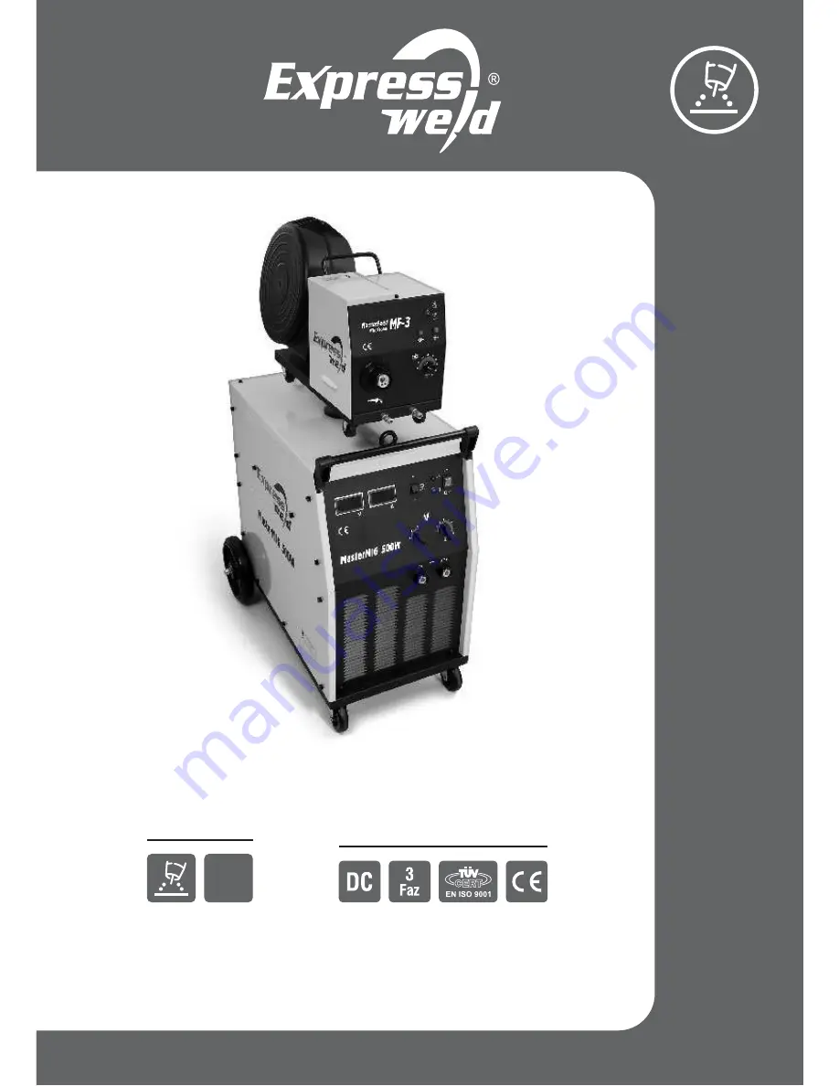
background image

Expressweld

MasterMIG 500W

Model :

www.

.com.tr

askaynak

Gas Metal

Arc W

elding Machine

Eczacıbaşı - Lincoln Electric recommend to use ASKAYNAK gas metal arc welding

wire for obtaining high performance from MasterMIG 500W.

USER GUIDE

Guarantee Period and Features

2 Years Guarantee (excl. torch and cables)

GMAW (MIG/MAG)

Welding Method

CO

2

Summary of Contents for MasterMIG 500W

Page 1: ...Arc Welding Machine Eczacıbaşı Lincoln Electric recommend to use ASKAYNAK gas metal arc welding wire for obtaining high performance from MasterMIG 500W USER GUIDE Guarantee Period and Features 2 Years Guarantee excl torch and cables GMAW MIG MAG Welding Method CO2 ...

Page 2: ...li belirtilen kaynak makinesinin ş ğı declares that the welding machine erklärt daß die Bauart der Maschine déclare que le poste de soudage EXPRESSWELD MasterMIG 500W a a da belirtilen yönergelere uygun oldu unu ş ğı ğ conforms to the following directives den folgenden Bestimmungen entspricht est conformé aux directives suivantes 2004 108 EC 2006 95 EC ve yine a a da belirtilen normlara uygun olar...

Page 3: ...intenance repair work of your product should be performed by authorized personnel To get optimized efficiency from your welder before starting your machine please carefully read and understand the user guide and keep it as a supplementary resource for future reference Failing to follow the instructions within the user guide may cause serious injury and damage on the machine Therefore we recommend ...

Page 4: ... Expressweld Expressweld is the registered trademark of Kaynak Tekniği Sanayi ve Ticaret A Ş Expressweld MasterMIG 500W ...

Page 5: ... MasterMIG is the registered trademark of Kaynak Tekniği Sanayi ve Ticaret A Ş Expressweld MasterMIG 500W ...

Page 6: ... Environment Conditions 12 Receiving Welding Machine From Service 13 GMAW MIG MAG Method 14 Productive Usage In Terms of Energy Consumption 15 Storage and Transportation 16 Maintenance and Repair 17 Unpacking 18 Troubleshooting Guide 19 Failures in Welding Seams 20 Spare Part List 21 Warning Label 22 Electrical Circuit Diagram 23 Wire Feeder and Power Unit Specifications TECHNICAL SERVICES 1 12 14...

Page 7: ...RUCTIONS CAREFULLY Be sure to read and understand the user guide before operating the machine Failure to follow the instructions stated in the user guide may cause serious injury loss of life and damage on equipment Do not weld while you are unattentive unattentive tired and sleepless Arc welding is a safe application when necessary measures are taken to protect the welder against potential danger...

Page 8: ...dition to provide some insulation against electric shock care should be taken that the gloves made from flame resistant material are in good condition and dry Noise To protect ears against sparks and melted metals and to prevent hearing impairment due to noise of arc welder ear protectors should be used When the noise in working environment is reached to a level that disturbing the ears and causin...

Page 9: ...ectric shock danger Electric shock risk related to welding machine divides into two categories Primary voltage shock e g 230 460 V Secondary voltage shock e g 20 100 V Primary electric shock is very dangerous since it is much higher than welding voltage When the power to the machine is open you can encounter with primary electric shock while your body is in contact with ground or touching a live p...

Page 10: ...de from flame resistance material Protect other nearby personnel with suitable non flammable screening and or warn them not to watch the arc nor expose themselves to the arc rays or to hot spatter or metal When eyes are exposed to UV rays even for a short time also called as Getting Welder s Flash it may cause burns in your eyes Getting Welder s Flash may not be noticed after hours of exposing but...

Page 11: ...and gases that are injurious to health Always enough ventilation should be used or fumes and gases should be exhausted from breathing place Generally in welding applications temporary effects for short time can be seen such as face and skin burning dizziness nausea and fever based on exposure period and amount of fume Long time fume exposure may cause iron loading and dysfunctions in lungs Bronchi...

Page 12: ...il Keep away fire hazards from welding area and have a fire extinguisher readily available Remember that welding sparks and hot materials from welding can easily go through small cracks and openings to adjacent areas Until ensuring that precautions are used to fully clean flammable and toxic gases never weld any tanks drums containers or material Never operate welder in places that flammable gases...

Page 13: ...piece If you are welding within ten meters to the place where flammable materials located have a observor near you This observer should watch where the sparks and splashes go and should access easily to the fire extinguishers when necessary After welding process please check if there is any fume around for half an hour with the observer As in other emergency situations first rule is not to panic i...

Page 14: ...to touch a cylinder Keep your head and face away from the cylinder valve outlet when opening the cylinder valve Valve protection caps should always be in place and hand tight except when the cylinder is in use or connected for use including the transportation of the cylinder Always keep all safety guards coverings and equipments in place and maintain in good condition Always keep your hands hair c...

Page 15: ...o prevent the risk for every kind of arc glare and fire never leave the electrode holder on welding desk or any surface in contact with work clamp GROUNDING High amounts of heat may be produced from welding process Hot surfaces and material may cause serious burns While touching or moving this kind of material always wear gloves Electric current flowing through any conductor causes electromagnetic...

Page 16: ...the cables since the cost will be high to replace cables repair by using tubw with high insulation or similar Always check the insulations before every time you start the welder If you feel an electric shock always remember that this is a warning In such case before continue to work check your equipment working routines and working environment against electric shock If there is an abnormal situati...

Page 17: ...ulated welding cables route cables through insulated plastic channels if available Expressweld MasterMIG 500W welder has been designed and manufactured in compliance with safety rules required by TS EN 60974 1 standard To eliminate the safety risks all necessary precautions have been taken precautions that need to be taken by operator and users and all rules to be followed have been stated in the ...

Page 18: ...n industrial fields In case of using in living spaces to eliminate potential effects of electromagnetic waves it is necessary to use specific precautions User should certainly install and operate the machine as per the instructions included in the user guide In case any electromagnetic interference is detected user should take necessary precautions for this If necessary Kaynak Tekniği Sanayi ve Ti...

Page 19: ...dy and stand between the cables and pay attention that the cables are not on the grounded surfaces Work cable should be connected to the piece being welded as close as possible While welding keep the power unit in a place as far as possible Insulation of cables within the working area may reduce the electromagnetic interference This situation may be necessary for some special applications To reduc...

Page 20: ...efore operating Various welders or other electrical devices should be connected in series if they are using the same grounding line all machines or devices should be connected in parallel to each other Cross sectional area of the grounding cable of the welder should not be less than the cross sectional area of the cable in the mains input While welding do not change the position of Welding Voltage...

Page 21: ...cle that prevents ventilation or stops airflow Do not cover the machine while operating with paper cloth or similar objects While welding make sure that the cover of the wire drive unit is closed Dust and dirt may enter into machine This should be reduced as much as possible Do not operate the machine in extremely dusty locations and environments having water paint and oil particles and also grind...

Page 22: ... extension cord It is suitable for the high quality welding of low carbon structural steel and stainless steel used in contructions It enables welding without splashing problem with carbon dioxide C02 gas It has 30 graded 3x10 welding voltage setting By this way it is possible to precisely set the welding parameters Wire feed speed can be set It has 2 4 trigger option It has slow wire feed soft st...

Page 23: ...speed u range n Wire speed setting before welding Wire diameters Steel wire V type reels Flux cored wire V type notched reels Supply voltage and power of wire drive unit Maximum supply current Protection class Weight excl cables Dimensions Width x Height x Depth MasterMIG 500W 380 V 10 50 60 Hz 3 Phase 28 3 kVA 38 A 28 A 0 94 73 3 500 A 39 0 V 387 A 33 4 V 20 51 V 75 500 A 17 8 39 V 30 3x10 IP21S ...

Page 24: ...tage precise setting switch Welding voltage coarse setting switch Coolant pump power switch WARNING While welding changing welding voltage range may cause damage to the machine Therefore stop welding to change the voltage range Wire feeder unit front wheels Torch connection socket EURO Water inlet and outlet channels for connecting torch cooling water Wire feed speed setting button Wire feed speed...

Page 25: ...s cylinder rear wheel Coolant connection socket Wire feeder unit power connection socket Control cable connection socket Pin for placing wire feeder unit to power unit Wire feeder unit handle Shielding gas inlet socket Control cable connection socket Wire feeder unit power connection socket Shielding gas C02 heater fuse 8A Mains inlet energy cable Specification plate Shielding gas cylinder fixing ...

Page 26: ...ting spindle Wire feeder engine Pin slot for placing wire feeder unit to power unit rear wheels Welding wire reel connecting shaft and braking torque setting Welding wire reel protection cabinet cover Welding wire reel protection cabinet Water inlet and outlet channels for connecting torch cooling water Welding torch connection socket Wire inlet guide Wire outlet guide Wire drive reels 1 unit Expr...

Page 27: ...rol cable Wire feeder unit power connection cable WIRE FEEDER UNIT POWER UNIT Welding torch cable Work cable Work piece TORCH Mains inlet energy cable GAS REGULATOR SHIELDING GAS CYLINDER CARBON DIOXIDE GAS HEATER 24V 55W Place and secure the shielding gas cylinder to the platform ...

Page 28: ... Electric leakages constitutes death risk for human health Secure the gas cylinder and protect against risks such as rollover Remove the safety valve cover of gas cylinder and leave the cylinder valve open for a while to clean it from foreign materials Install the gas regulator on gas cylinder Connect the gas hose to gas regulator Connect the other end of gas hose to Shielding Gas Inlet Socket loc...

Page 29: ...n the rear of power unit and wire feeder unit to each other via Wire Feeder Unit Connection Cable To provide shielding gas to wire feeder unit and welding torch it is necessary to connect Shielding Gas Hose to Shielding Gas Inlet Socket located in the rear of wire feeder unit At the end of gas hose there is a pipe connection To provide the coolant flow which will be transmitted to the welding torc...

Page 30: ...he by loosening Run the welding wire through the of wire feeder unit Install the welding wire to by running through wire drive reels After setting the press force by fixing again the start the machine with located in the front panel of power unit Press the located in the front panel of wire feeder unit During this action always make sure that the contact nozzle of welding torch is not in place You...

Page 31: ...ngs tightened to the left braking torque increases when tightened to the right braking torque decreases Wire drive unit is equipped with V channeled reels set for Ø 0 8 1 0 and 1 2 mm solid welding wire For Ø 1 2 ve 1 6 mm flux cored there are Notched V channeled reels Make sure that the diameter of installed reel is suitable for the diameter of welding wire being used There is a mark on the side ...

Page 32: ...ng once the trigger on the welding torch When pressed second time welding stops With this button only wire feeder unit is started without starting power unit and gas solenoid This feature is used while driving the welding wire to welding torch With this button only the gas solenoid may be turned on and off without starting the power unit This feature is used for controlling the gas flow speed and ...

Page 33: ...d be contacted immediately When current circuit is locked or electric voltage is determined on the body procedure indicated in the fourth article should be performed Also in case of mechanical damage such as machine falls down from a high place again procedure indicated in the fourth article Extremely damp environment may cause damage to the insulation of the machine and electric shock danger Whil...

Page 34: ...is as good as possible Start the machine by turning the located in the front panel of the power unit to position will light up Welding voltage value is approximately set with and precisely set with Refer to the table on Page 21 These switches are located in front of the power unit Place the located in the front panel of the power unit to position Coolant pump will start to operate Value of welding...

Page 35: ...e On position While welding to prevent over energy consumption current values that are suitable for the used welding wire diameter should be used and current values higher than adequate should be avoided Welding machine should be stored at confined rooms having temperature between 20 C ile 55 C and at most 90 relative humidty rate at 20 C Room should be free from flammable conductive dust or other...

Page 36: ...ice over pressure decrease the press force setting as appropriate If wire drive reels are worn or damaged you cannot achieve a smooth wire feed Frequently check the reels and if there is any wear replace with the new ones Before installing a new welding wire reel remove the gas nozzle and contact nozzle and clean the spiral with compressed air This procedure will prevent the sticking of the wire C...

Page 37: ... dusts To protect small parts be carefull about the air pressure used in cleaning Check the screws on the machine and if they are loosen tighten If there is missing screw always install a new one Replace rusted screws with the new ones Check the conditions of all electric connections and tighten loosed connections when necessary Measure insulation impedance on main transformer PCB and body If the ...

Page 38: ... control cable Current setting potentiometer is faulty Change the potentiometer There is no energy in AC Contact with technical service Control board PC board is faulty Contact with technical service There is wire feeding and gas flow but there is no open circuit voltage Supply voltage value is too low under 350 V Check the supply voltage as to be 380 10 V One of the phases is missing in supply vo...

Page 39: ...ed Check the gas connection hose Gas solenoid is faulty Clean the electronic valve or replace with the new one Wire is curled within torch bended in feed reels or inlet guide End of the wire stucked to contact nozzle Change the contact nozzle and if necessary change the nozzle Inlet guide is too away from the wire feed reels or guides are blocked Check the distance Perform necessary adjustments Cl...

Page 40: ...fans open doors etc When welding with C02 gas to prevent clogging of the regulator due to freezing use heater or connect several gas cylinders to eachother Decrease the advancing speed Decrease the distance between nozzle and workpiece Until molten metal become solid keep the torch at the end of the welding seam 2 Use a quality gas manufactured for welding Adjust the gas flow rate 3 Only use clean...

Page 41: ...access to root of seam Route the welding wire to the front of weld puddle Adjust the torch angle in corner welding 5 To enable access to seam soul adjust combination angle properly To fuse seam corners adjust free wire length or prepare J or U seam 6 Decrease wire feed speed 1 To access to the soul of seam with the condition to provide correct free wire length and arc characteristics revise connec...

Page 42: ...g the inductance in welding machine 2 Decrease the arc voltage or immerse the arc by increasing the wire feeding speed so limit the splashing 3 By increasing the current enter into spray conduction mode Edge Burn Possible Reasons 1 Advancing speed is too high 2 Welding voltage is too high 3 Welding current is too high 4 Waiting time is insufficient 5 Torch angle is wrong Solutions 1 Decrease the a...

Page 43: ...20 Spare Part List Power Unit Expressweld MasterMIG 500W Page 37 ...

Page 44: ... 9 10 11 12 13 14 15 16 17 18 19 20 21 22 23 24 25 26 27 28 29 30 31 8220752020 8220752028 8211150008 8220430104 8220754122 8220757822 8220757124 8220129006 8212435510 8220757757 8220757756 8220752019 8220741602 8212450907 8220780972 8220789027 8220501018 8220501021 8212450925 8212450922 8212450934 8212450932 8220614404 8220507108 8212450906 8212450910 8212450913 8212450912 8212450921 8220737452 8...

Page 45: ...8 39 40 41 42 43 44 45 46 47 48 49 50 51 52 53 54 55 56 57 8220742006 8212450926 1 8220780213 8220728209 8220728211 8220780211 8220746553 8220780566 8220780569 8220131062 8212450215 8220131061 8212450933 8212450931 8220431107 8212450909 8212435808 8211110372 8212425005 3 8212435810 8220741081 8220431105 8212450911 8250201045 8220604010 8212450905 Part Code ERP Code 2 07 42 006 1 24 509 26 1 2 07 8...

Page 46: ...Wire Feeder Unit Expressweld MasterMIG 500W Page 40 ...

Page 47: ...1 12 13 14 15 16 17 18 19 20 21 22 23 24 25 26 27 28 29 30 31 32 33 8220505301 8220505101 8212406213 1 8212406212 1 8250202808 8220755006 8212406212 2 8220754104 8220757117 8212406212 3 8220757813 8212435801 8212435802 8220802200 8222012521 8220757819 8212406204 8220507313 8220802004 8212406210 8250202005 8220507314 8212406211 8220710043 8220711009 8212406209 1 8212406205 8220780634 8220505015 822...

Page 48: ...06 8222001008 8220740314 8220740315 8220740316 8222009606 8220754120 8220754130 Part Code ERP Code 2 07 51 703 2 07 40 312 2 05 06 012 2 05 06 011 1 24 050 06 1 24 062 08 2 07 11 006 2 20 01 008 2 07 40 314 2 07 40 315 2 07 40 316 2 20 09 606 2 07 54 120 2 07 54 130 Expressweld MasterMIG 500W 21 Warning Label Page 42 BEFORE STARTING and OPERATING THIS EQUIPMENT READ OPERATION INSTRUCTIONS TO INSTA...

Page 49: ...agram Machine control circuit connection diagram Water pressure sensor Switch Alarm Heater Water Engine Electrical power indicator Wire feeder unit circuit Wire feeding socket Engine Solenoid AC 42V Torch switch Gas control switch Current control switch Burnback time Slow wire feeding Wire feeding speed without welding H zı ı Off On EXPRESSWELD MasterMIG 500W connection diagram Expressweld MasterM...

Page 50: ...XPRESSWELD TOSB Taysad Org San Bölgesi 2 Cadde No 5 41480 Çayırova Kocaeli TURKEY Wire Feeder Unit Power unit Kaynak Tekniği Sanayi ve Ticaret A Ş EXPRESSWELD TOSB Taysad Organize San Bölgesi 2 Cadde No 5 Şekerpınar41480 Çayırova Kocaeli TURKEY MasterMIG 500W Model Serial Number TS EN 60974 1 TS EN 60974 10 110 A 19 5 V 500 A 39 V X I2 U2 60 100 500 A 387 A 39 V 33 4 V U0 20 51 V IP21S cos 0 94 50...

Page 51: ... ı ı Sanayi ve Ticaret Ltd ti Ş 1426 Sokak No 14 Bornova ZM R İ İ TURKEY Phone 0232 478 14 12 Fax 0232 479 64 77 e mail hasan dorukhirdavat com tr ERMA Teknik Malzeme Ticaret ve Sanayi Ltd ti Ş 4 Sanayi Sitesi 129 8 Sokak No 2 Bornova ZM R İ İ TURKEY Phone 0232 375 52 83 Fax 0232 375 60 59 e mail ermateknikltd superonline com KAHRAMANMARA Ş Kahraman Bobinaj Yeni Sanayi Sitesi 25 Çar No 8 şı KAHRAM...

Page 52: ...stanbul İ İ Turkey Phone x 0216 395 84 50 395 56 77 Fa 0216 395 84 02 İZMİR Regional Sales Office Mersinli Mahallesi 1 Sanayii Sitesi 2822 Sokak No 25 35120 zmir İ Turkey Phone x 0232 449 90 35 449 01 64 Fa 0232 449 01 65 ANKARA Regional Sales Office Ostim Sanayii Sitesi Ahi Evran Caddesi No 83 06370 Ostim Ankara Turkey Phone x 0312 385 13 73 pbx Fa 0312 354 02 84 ADANA Regional Sales Office K z l...

Reviews: