background image


35280 f - GB/FR/NL/ES/PT/PL 


RAFALE REPLACEMENT PARTS INSTRUCTIONS


GENERAL PRECAUTIONS FOR USE


READ THIS MANUAL CAREFULLY IN ITS ENTIRETY 

AND RETAIN IT IN A SAFE PLACE FOR FUTURE REFERENCE. 


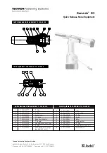
PIEZO IGNITION KIT - Item. 35242 

- Vent the hose, disconnect the equipment.


- Take the hex spanner supplied with the equipment 

- Unscrew the 4 screws from the gun and withdraw  

  them 

Lift off the cover by the guard 

Lift off the trigger vertically 

Lift out the pin 

Take out the piezo ignition unit 

-


Position the stripped part of the wire in the housing. Fit the rigid ignition wire coming from the rear of   

   the equipment in this location, and refit the split pin


D, 

-


Position the piezo ignition unit with the head against the spring 

-


Refit the trigger with the piezo unit horizontal 

- Refit the cover in position with the notch in the rear opening 

Replace the four screws. 

-


Tighten until the components are closed together (tighten firmly but not excessively) 

- Check for correct operation: 

With the equipment still disconnected from the cylinder

 move to a  

  darkened area. Check that a good spark is produced in the brass cup at the centre of the burner. 

Item. 35241 

Item. 35242 
Item. 35243 
Item. 35244 

Item. 35088 

Item. 35198 

GB/FR/NL/ES/PT/PL 

The  replacement  parts  for  the  RAFALE  and 

RAFALE  +  range  of  equipment  are  intended 

only professional applications and must only be 

used by users who are trained in their use.  

With  the  exception  of  the  list  of  replacement 

parts supplied by Express, for safety reasons all 

other  repairs  must  be  undertaken  by  the 

manufacturer  and  distributors.    Failure  to 

observe  this  clause  will  result  in  the  guarantee 

being null and void. 


It is essential that you read this 

manual before use. 


Summary of Contents for RAFALE Series

Page 1: ...piezo unit horizontal C Refit the cover in position with the notch in the rear opening B Replace the four screws A Tighten until the components are closed together tighten firmly but not excessively Check for correct operation With the equipment still disconnected from the cylinder move to a darkened area Check that a good spark is produced in the brass cup at the centre of the burner Item 35241 I...

Page 2: ... tighten the screw on the burner BURNER KIT Item 35244 HOOK REPLACEMENT To replace the hook in the event of it being lost or damaged Place the first part of the hook in the hole in the handle pull on the second part so that it locates in its housing Changing the burner Loosen the knurled screw located on the handle Carefully withdraw the burner Place the burner in the handle Tighten the knurled sc...

Page 3: ...s Replace the hose item 35241 Re tighten the nut on the regulator using two open ended spanners tighten firmly to a torque of 16 N m Do not just hand tighten only Re connect the quick connector to the equipment Carry out the start up checks Remark for an explanation of the hose manufacture date and for further details please refer to the EXPRESS ISO 3821 Hose technical data sheet DEFLECTOR Item 35...

Page 4: ...eformation of the body of the protection wires or of the burner no damage to threads etc This guarantee does not include consumables such as the hose the automatic igniter and the ignition wire 3 Guilbert Express will guarantee exchange for a reconditioned item of equipment in the event of a manufacturing fault or during the first two years following the purchase of the equipment The guarantee is ...

Reviews: