Exmark QUEST QZS708GEM50200, Operator'S Manual
The Exmark QUEST QZS708GEM50200 Operator's Manual is a invaluable resource for owners of this exceptional product. Easily downloadable and available for free from manualshive.com, this comprehensive manual offers essential instructions and guidelines for maintaining and operating your Exmark QUEST QZS708GEM50200.
Share
Download


Reviews:
No comments
Related manuals for QUEST QZS708GEM50200

Silver Series
Brand: Lawn-Boy Pages: 84

TT 300 S
Brand: Wolf Garten Pages: 46

247.375770
Brand: Yard-Man Pages: 24

Cheetah SCZ48V-22FX
Brand: Scag Power Equipment Pages: 78
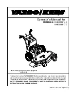
KHKW36140
Brand: Yazoo/Kees Pages: 19

ZYJ-1361-A
Brand: Yard-Man Pages: 6

GTM 155
Brand: Gianni Ferrari Pages: 96

ULTRAVAC BAGGER
Brand: Exmark Pages: 19

27706
Brand: Craftsman Pages: 68

2508
Brand: Simplicity Pages: 4

1691735
Brand: Simplicity Pages: 15

1500 Series
Brand: Simplicity Pages: 40

FB
Brand: Simplicity Pages: 24

WONDER-BOY 400
Brand: Simplicity Pages: 38

576
Brand: Simplicity Pages: 8

46" Single Stage Snowthrower - Body &
Brand: Simplicity Pages: 6

350
Brand: Simplicity Pages: 16

7800071
Brand: Simplicity Pages: 38


