background image


EQL-215 


Egaliseur 2 x 15 Bandes 


    Equalizer 2 x 15 Bands 


NOTICE D’UTILISATION 

USER MANUAL 


Summary of Contents for EQL-215

Page 1: ...EQL 215 Egaliseur 2 x 15 Bandes Equalizer 2 x 15 Bands NOTICE D UTILISATION USER MANUAL ...

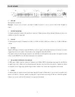
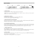
Page 2: ...iliser cette fonction pour comparer votre installation en mode équalisé ou non équalisé Vous pouvez de même utiliser le mode BY PASS en cas de disfonctionnement de votre équaliseur 5 PEAK INDICATEUR DE SURCHARGE La LED rouge s allume si une des sections de l égaliseur est à 5 dB du CLIP Un clignotement occasionnel de cette LED est acceptable mais si elle s allume avec des intermittences plus fréqu...

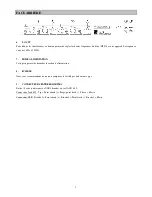
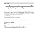
Page 3: ...ALIMENTATION Cette prise permet de brancher le cordon d alimentation 8 FUSIBLE Nous vous recommandons de toujours remplacer le fusible par un de même type 9 CONNECTEURS ENTREES SORTIES Entrée Sortie symétrique sur XLR 3 broches ou sur JACK 6 35 Connecteur Jack 6 35 Tip Point chaud Ring point froid Sleeve Masse Connecteur XLR Broche 2 Point chaud Broche 3 Point froid Broche1 Masse ...

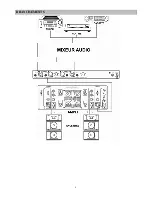
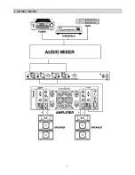
Page 4: ...4 BRANCHEMENTS ...

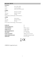
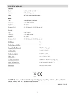
Page 5: ...ype Relais symétrique Connecteurs XLR 3 PIN JACK 6 35 Impédance 600 Ohms Niveau maximum 22dB Symétrique 15dB Asymétrique FILTRES RFI Oui SWITCH PASSIF BY PASS Oui SEUIL SURCHAGE 3dB Avant coupure FILTRE LOW CUT 10 250Hz 12dB Oct REPONSE DE FREQUENCE 20 20kHz 0 5dB THD BRUIT 0 01 20Hz 40 kHz RATIO SIGNAL BRUIT 110dB en dessous du niveau max BRUIT ENTREE EQUIVALENT 95dB 20kHz bruit largeur de bande ...

Page 6: ...is illuminated this indicates that the unit or channel is in the bypass mode Signal is routed directly from the input to the output without passing through any circuit often referred to as hard wire bypass Use this switch to compare equalized and unequalized material or to bypass the EQ section in the event of power loss or unit failure 5 OVERLOAD INDICATOR This red LED illuminates if any section ...

Page 7: ...o connect the AC power source to your equalizer CAUTION DO NOT REMOVE THE CENTER GROUNDING PIN 9 FUSE HOLDER This fuse holder contains an AC primary fuse This fuse should be replaced by the same type fuse when this is blown out If they continuously blow stop replacing fuse and refer servicing to qualified personnel 10 INPUT OUTPUT CONNECTORS 1 4 TRS The TRS Tip Ring Sleeve connector is balanced an...

Page 8: ...8 CONNECTIONS ...

Page 9: ...Maximum Level 22dB Balanced 15dB Unbalanced RFI Filters Yes Passive Bypass Switches Yes Overload LED Threshold 3dB Below Clipping Low Cut Filter 10 250Hz 12dB Oct Frequency response 20 20kHz 0 5dB THD Noise 0 01 20 Hz 40 kHz Signal to Noise Ratio 110dB below Max Level A weighting Equivalent Input Noise 95dB 20 kHz Noise Bandwidth Dimensions 44 5mm 483mm 216mm CAUTION The apparatus shall not be exp...

Reviews: