Eurotherm 5100e, User Manual
The Eurotherm 5100e is a high-performance device designed for precise temperature control. To ensure easy operation, we provide a comprehensive User Manual for free download from our website. This manual guides users through the setup and calibration process, enabling optimized utilization of the product's capabilities.
Share
Download


Reviews:
No comments
Related manuals for 5100e

DMD-F101
Brand: Denon Pages: 36
DM-9090
Brand: Kenwood Pages: 56
DM-5090
Brand: Kenwood Pages: 56
1090MD
Brand: Kenwood Pages: 56
DM-B9
Brand: Kenwood Pages: 40
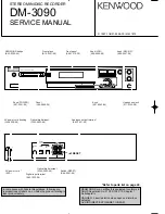
DM-3090
Brand: Kenwood Pages: 48
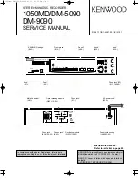
1050MD
Brand: Kenwood Pages: 40

E36
Brand: Aiworth Pages: 20

VOICE MAGIC
Brand: Maycom Pages: 33

VR8204
Brand: SB Pages: 22

DVR-2100
Brand: Astar Pages: 24

OBSERVER 4112 HVR
Brand: Safety Vision Pages: 15

DVR313 Series
Brand: Zenith Pages: 69

DS 30
Brand: Olympus Pages: 163

DMR-E30S
Brand: Panasonic Pages: 6

DMR-E60S
Brand: Panasonic Pages: 6

RRUS591 - IC RECORDER
Brand: Panasonic Pages: 44

AG-HPX171EJ
Brand: Panasonic Pages: 132


