background image

EMI-EMP Filter

Signal / Control / Data

Installation and Maintenance Manual

1703315 Rev C

December 2019

Summary of Contents for EMI

Page 1: ...EMI EMP Filter Signal Control Data Installation and Maintenance Manual 1703315 Rev C December 2019 ...

Page 2: ......

Page 3: ...license under its patent rights nor the rights of others All trademarks are the property of their respective owners Copyright 2019 by ETS Lindgren Inc All Rights Reserved No part of this document may be copied by any means without written permission from ETS Lindgren Inc Trademarks used in this document The ETS Lindgren logo is a registered trademark of ETS Lindgren Inc Revision Record MANUAL EMI ...

Page 4: ...4 ...

Page 5: ...ces If Provided 10 Automatic Discharge 10 Shorting Stick Not Provided 11 ELECTRICAL PERFORMANCE CHARACTERISTICS 11 Voltage RMS 11 Voltage Drop 11 Overload Current 11 Insertion Loss Stop Band 11 Current 11 Frequency of Operation Pass Band 11 ENVIRONMENTAL SPECIFICATIONS 12 INSTALLATION 12 POWER ON 12 MAINTENANCE 13 Inspection and Cleaning of Wiring Compartments 13 Capacitance Measurement and MOV In...

Page 6: ...6 ILLUSTRATIONS 15 Filter Penetration 15 Filter Installation on Shield 16 Filter Electrical Wiring 16 Individually Mounted Filters 16 Panelized Filters 16 WARRANTY STATEMENT 21 ...

Page 7: ...al for additional information If the instruction manual has been misplaced download it from www ets lindgren com or contact ETS Lindgren Customer Service High Voltage Indicates presence of hazardous voltage Unsafe practice could result in severe personal injury or death High Voltage Indicates presence of hazardous voltage Unsafe practice could result in severe personal injury or death Protective E...

Page 8: ...e servicing contact ETS Lindgren servicing or modifying the unit by yourself may void your warranty If you attempt to service the unit by yourself disconnect all electrical power before starting There are voltages at many points in the instrument which could if contacted cause personal injury Only trained service personnel should perform adjustments and or service procedures upon this instrument C...

Page 9: ...lletin See the ETS Lindgren Product Information Bulletin included with your shipment for the following Warranty information Safety regulatory and other product marking information Steps to receive your shipment Steps to return a component for service ETS Lindgren calibration service ETS Lindgren contact information PRECAUTIONS LETHAL VOLTAGES PRESENT THIS UNIT SHOULD BE INSTALLED AND MAINTAINED BY...

Page 10: ...ut conductors are brought into the clean side wiring compartment of the filter through a conduit penetration if provided or a circular opening in the back of the filter panel The conductors should then be directly terminated to the filter terminals or lugs if provided or equivalent The output terminals of the filter are EMI isolated from the inputs Filter Penetrations All filter penetrations inclu...

Page 11: ...ARACTERISTICS Voltage RMS According to filter label as applicable to each individual filter type Voltage Drop The total AC voltage drop from input to output is designed to be no more than 2 of the rated voltage when measured into a unity power factor Overload Current The filter can withstand an overload current of 1 4 times the rated current in amperes for a period of fifteen 15 minutes and mainta...

Page 12: ... be performed by a qualified electrician and in compliance with all applicable regulatory agencies Connection to the filter should be made by qualified electricians Refer to the TERMINATIONS section for further details Wiring should be done in accordance to the wiring schematic provided in the ILLUSTRATIONS section of this manual and applicable local and national electrical codes and guidelines In...

Page 13: ...AND CLEANING OF WIRING COMPARTMENTS procedure after an event that causes abnormal contamination of filter wiring compartments with liquid or debris Follow the CAPACITANCE MEASUREMENT AND MOV INSPECTION PROCEDURE following an event that causes abnormal voltage overloads or spikes beyond that which the filters are designed to accommodate Frequency of maintenance is at the discretion of the user and ...

Page 14: ...l 4030 01 or equivalent to determine if they are operational Replacement is required if they are not operational 10 Measure the line to ground capacitance of each phase Using an LCR bridge measure the capacitance of each phase at 120 Hz Contact ETS Lindgren for expected values please provide model number of filter The reading should be according to these values 20 A DF measurement should be done a...

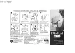
Page 15: ...15 ILLUSTRATIONS Filter Penetration Filter penetrations should be installed as shown ...

Page 16: ... the terminal Soldering iron should not exceed 60W An input terminal corresponds to an output terminal on the same line Panelized Filters These filters will be pre wired to a set of DIN terminals on rails at the bottom of the cabinet panel Connection is made to the DIN terminals by means of screwing a wire to them Yellow Green DIN terminals are grounded points Installation on shield is straight fo...

Page 17: ...17 General illustration of an individually mounted signal filter General illustration of a signal line panel filter ...

Page 18: ...18 Individually mounted 4 line signal filter Individually mounted 2 line signal filter ...

Page 19: ...19 Panel signal filter Individually mounted 10 to 12 line signal filter ...

Page 20: ...20 ...

Page 21: ... s installation Procedure nor does it extend to any portion of the material which has been repaired or altered by other than the Seller The Buyer upon request shall furnish to the Seller reasonable evidence that the defect arose from causes other than those contained in the preceding sentence THIS WARRANTY IS EXCLUSIVE NO OTHER WARRANTY WRITTEN OR ORAL IS EXPRESSED OR IMPLIED INCLUDING BUT NOT LIM...

Page 22: ......

Reviews: