background image

Instruction Sheet 

1 of 8 

© 2022 TE Connectivity Ltd. family of companies. 
All Rights Reserved. 
  

TE Connectivity, TE connectivity (logo), and TE (logo) are trademarks.  Other logos, product, and/or company names may be trademarks of their respective owners. 

PRODUCT INFORMATION 1-800-522-6752 

This controlled document is subject to change. 
For latest revision and Regional Customer Service, 
visit our website a

www.te.com

408-35141 

15 JUL 2022  Rev B

PROPER USE GUIDELINES


Cumulative trauma disorders can result from the prolonged use of manually powered hand tools. Hand tools are intended for occasional 
use and low-volume applications. A wide selection of powered application equipment is available for extended-use production operations. 
The SDE-SA hand tool is a commercial-grade tool. Product crimped with this tool meets the wire barrel crimp height requirement for hand 
tools in the appropriate 114 application specification but might not comply with other feature parameters of the specification. 

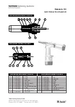
Figure 1: SDE-SA Commercial Hand Tool Assembly 2383863-1 with Die Assembly 2383863-2 


Die set 2383863-2 

Flip locator assembly 

11 

Handle 

Wire crimper (upper die) 

Nut 

12 

Die-retaining screws (2) 

Insulation crimper (upper die) 

Stationary jaw 

13 

Die-retaining spring pins (4) 

Wire anvil (lower die) 

Moving jaw 


Insulation anvil (lower die) 

10 

Ratchet adjustment wheel 


SDE-SA Commercial Hand Tool Assembly 

PN 2383863-1 with 

Die Assembly PN 2383863-2 


Summary of Contents for SDE-SA

Page 1: ...ons A wide selection of powered application equipment is available for extended use production operations The SDE SA hand tool is a commercial grade tool Product crimped with this tool meets the wire barrel crimp height requirement for hand tools in the appropriate 114 application specification but might not comply with other feature parameters of the specification Figure 1 SDE SA Commercial Hand ...

Page 2: ...kets Figures are for reference only and are not drawn to scale Read these instructions thoroughly before crimping connectors 2 DESCRIPTION The tool frame features two jaws a handle and a ratchet adjustment wheel The die set consists of a crimper upper die and an anvil lower die The tool frame holds a die assembly with three crimping chambers see Figure 1 Die retaining spring pins and screws are us...

Page 3: ... and through the crimper dies Tighten the screw just enough to hold the die in place Do not tighten the screw completely 9 Carefully close the tool handles making sure the anvil and crimper align properly Continue closing the tool handles until the ratchet in the tool frame has engaged sufficiently to hold the dies in place 10 Tighten both die retaining screws 11 Place the flip locator assembly ov...

Page 4: ... Strip the wire to the length indicated Do not nick or cut wire strands 3 Select an applicable contact and identify the appropriate crimp section according to the wire size markings on the tool 4 Hold the tool so that the back wire side is facing you Figure 2 Squeeze the tool handles together and allow them to open fully Figure 2 Flip locator 1 Die assembly for reference only 2 Flip locator 3 Back...

Page 5: ...te the locator towards the anvils to place the terminal on the anvil CAUTION Make sure that both sides of the wire barrel are started evenly into the crimping section Do not attempt to crimp an improperly positioned contact 9 Close the handles of the tool until the contact is lightly held by the die set but is not deformed to the point where the wire cannot enter freely 10 Insert the wire into the...

Page 6: ...maximum size for each crimp section listed 2 Refer to section 5 CRIMPING and crimp the contacts accordingly 3 Using a crimp height comparator measure the wire barrel crimp height listed in Table 2 If the crimp height conforms to that shown in the table the tool is considered dimensionally correct If not adjust the tool Refer to section 7 ADJUSTING THE RATCHET CAUTION Do not use damaged product If ...

Page 7: ...m to the recommended crimp height replace the tool or die set See section 9 REPLACEMENT AND REPAIR Figure 6 Ratchet adjustment 1 Adjustment screw 2 Ratchet adjustment wheel 8 MAINTENANCE AND INSPECTION 8 1 Maintenance Remove dust moisture and other contaminants with a clean soft brush or soft lint free cloth Do not use objects that could damage the dies or tool Remove all lubrication and accumulat...

Page 8: ... order parts by any of the following methods Go to TE com and click the Shop TE link at the top of the page Call 800 522 6752 Write to CUSTOMER SERVICE 038 035 TE CONNECTIVITY CORPORATION PO BOX 3608 HARRISBURG PA 17105 3608 For customer repair services call 800 522 6752 10 REVISION SUMMARY Revisions to this instruction sheet include Updated to use new tool frame and flip locator ...

Reviews: