


ISO 9001 ISO 14001
Producent / Producer /
Производитель
Zakłady Metalowe ERKO R. P
ę
tlak spółka jawna
Bracia P
ę
tlak
ul. Ks. Jana Hanowskiego 7, 11-042 JONKOWO k/OLSZTYNA
tel./fax (+48) 089 5129273 NIP: 739-020-46-93
e-mail: [email protected], [email protected] serwis informacyjny: www.erko.pl.
OPERATION MANUAL
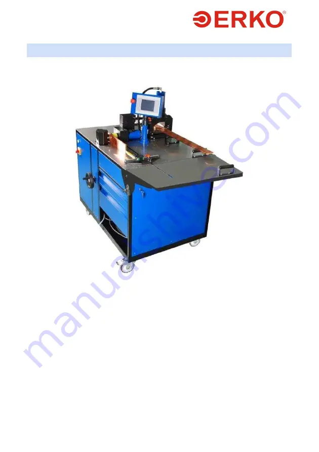
BUSBAR PROCESSING SITE
SH400PLC TYPE
SWW 0792 #VSH400PLC090909 PKWiU 29.56.25-90.00


