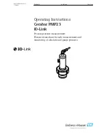
background image

Products

Solutions

Services

Operating Instructions

Cerabar PMP23

IO-Link

Process pressure measurement

Pressure transducer for safe measurement and

monitoring of absolute and gauge pressure

BA01784P/00/EN/01.17

71378480

Summary of Contents for Cerabar PMP23

Page 1: ... Solutions Services Operating Instructions Cerabar PMP23 IO Link Process pressure measurement Pressure transducer for safe measurement and monitoring of absolute and gauge pressure BA01784P 00 EN 01 17 71378480 ...

Page 2: ... it is always available when working on or with the device To avoid danger to individuals or the facility read the Basic safety instructions section carefully as well as all other safety instructions in the document that are specific to working procedures The manufacturer reserves the right to modify technical data without prior notice Your Endress Hauser distributor will supply you with current i...

Page 3: ...9 7 1 Operation with an operating menu 19 8 System integration 20 8 1 Process data 20 8 2 Reading out and writing device data ISDU Indexed Service Data Unit 20 8 3 Overview of diagnostic events 22 9 Commissioning 23 9 1 Function check 23 9 2 Commissioning with an operating menu 23 9 3 Configuring pressure measurement 24 9 4 Performing position adjustment 26 9 5 Configuring process monitoring 28 9 ...

Page 4: ...situation can result in serious or fatal injury CAUTION CAUTION This symbol alerts you to a dangerous situation Failure to avoid this situation can result in minoror medium injury NOTICE NOTICE This symbol contains information on procedures and other facts which do not result in personalinjury 1 2 2 Electrical symbols Symbol Meaning Symbol Meaning Protective ground connection A terminal which must...

Page 5: ...bol Meaning 1 2 3 Item numbers 1 2 3 Series of steps A B C Views 1 3 Documentation The document types listed are available In the Download Area of the Endress Hauser Internet site www endress com Download 1 3 1 Technical Information TI planning aid for your device TI01203P The document contains all the technical data on the device and provides an overview of the accessories and other products that...

Page 6: ...est rated element with regard to pressure of the selected components i e the process connection has to be taken into consideration in addition to the measuring cell Also observe pressure temperature dependency For the relevant standards and additional notes see the Pressure specifications section 66 The MWP may be applied at the device for an unlimited period The MWP can also be found on the namep...

Page 7: ...sor 10 bar 150 psi Upper range value URL 10 bar 150 psi Turn down TD Calibrated adjusted span 0 to 5 bar 0 to 75 psi Lower range value LRV 0 bar 0 psi Upper range value URV 5 bar 75 psi TD URL URV LRV TD 10 bar 150 psi 2 5 bar 75 psi 0 bar 0 psi In this example the TD is 2 1 This span is based on the zero point 1 6 Registered trademarks is a registered trademark of the IO Link company group ...

Page 8: ...2 Designated use 2 2 1 Application and media The Cerabar is used to measure absolute and gauge pressure in gases vapors and liquids The process wetted materials of the measuring device must have an adequate level of resistance to the media The measuring device may be used for the following measurements process variables in compliance with the limit values specified under Technical data in complian...

Page 9: ...despite this modifications are required consult with Endress Hauser Hazardous area To eliminate the risk of danger to persons or the facility when the device is used in the approval related area e g pressure equipment safety Check the nameplate to verify if the device ordered can be put to its intended use in the approval related area 2 5 Product safety This measuring device is designed in accorda...

Page 10: ...housing cap D E A0027227 D E Housing Process connection sample illustration 3 2 Function 3 2 1 Calculating the pressure Devices with metallic process isolating diaphragm The process pressure deflects the metal process isolating diaphragm of the sensor and a fill fluid transfers the pressure to a Wheatstone bridge semiconductor technology The pressure dependent change in the bridge output voltage i...

Page 11: ...RY NOTE 1 2 A0016870 Is the order code on the delivery note 1 identical to the order code on the product sticker 2 A0022100 A0028673 A0022103 Are the goods undamaged A0028673 DELIVERY NOTE A0022105 Do the data on the nameplate correspond to the order specifications and the delivery note If one of these conditions does not apply please contact your Endress Hauser sales office ...

Page 12: ...on provided enter the serial number from the nameplates in W M Device Viewer www endress com deviceviewer 4 2 1 Manufacturer address Endress Hauser GmbH Co KG Hauptstraße 1 79689 Maulburg Germany Address of the manufacturing plant See nameplate 4 2 2 Nameplate Ser no Ord cd Ext ord cd D 79689 Maulburg Made in Germany Cerabar 5 1 2 3 4 Date TAG A0024456 1 Manufacturer s address 2 Device name 3 Orde...

Page 13: ...ss Hauser 13 4 3 2 Transporting the product to the measuring point LWARNING Incorrect transport Housing and diaphragm may become damaged and there is a risk of injury Transport the measuring device to the measuring point in its original packaging or by the process connection ...

Page 14: ...ensation water Protect housing against impact For devices with gauge pressure sensor the following applies NOTICE If a heated device is cooled in the course of a cleaning process by cold water for example a vacuum develops for a short time causing moisture to penetrate the sensor via the pressure compensation element 1 Device could be destroyed In the event of this happening mount the device in su...

Page 15: ...asurement in vapors For pressure measurement in vapors use a siphon The siphon reduces the temperature to almost ambient temperature Mount the device with a shutoff device at the same height as the tapping point Advantage only minor negligible heat effects on the device Note the max permitted ambient temperature of the transmitter 1 2 3 A0024395 1 Device 2 Shutoff device 3 Siphon Pressure measurem...

Page 16: ...ng adapter For details on mounting see KA00096F 00 A3 5 6 Post installation check Is the device undamaged visual inspection Does the device comply with the measuring point specifications For example Process temperature Process pressure Ambient temperature range Measuring range Are the measuring point identification and labeling correct visual inspection Is the device adequately protected against p...

Page 17: ...ve circuits against reverse polarity are integrated Connect the device in the following order 1 Check that the supply voltage corresponds to the supply voltage indicated on the nameplate 2 Connect the device in accordance with the following diagram Switch on the supply voltage Device M12 plug PMP23 C Q L L 2 1 3 4 SIO IO Link A0034006 1 Supply voltage 2 4 20 mA 3 Supply voltage 4 C Q IO Link commu...

Page 18: ...xceeded depending on the supply voltage UB of the supply unit W 20 30 10 0 1022 587 152 U V 1 2 R R L L max max U 6 5V 23mA B B A0031107 1 Power supply 10 to 30 V DC 2 RLmax Maximum load resistance UB Supply voltage Error current is output and S803 displayed output MIN alarm current Periodic checking to establish if it is possible to quit fault state 6 4 Post connection check Is the device or cabl...

Page 19: ...ring device while in operation Physical layer the measuring devices supports the following features IO Link specification version 1 1 IO Link Smart Sensor Profile 2nd Edition SIO mode yes Speed COM2 38 4 kBaud Minimum cycle time 2 5 msec Process data width 24 bit IO Link data storage yes Block configuration no IO Link download http www endress com download Select Software as the media type Select ...

Page 20: ...tput Here 1 or DC 24 V corresponds to the logical closed state on the switch output The remaining 22 bits contain the analog raw measured value of the device This value has yet to be scaled by the target system to the nominal operating range of the existing measuring device Bit Process value Value range 22 OU1 0 open 1 closed 0 to 21 Raw value Int22 The decimal separator must be determined using a...

Page 21: ...2 0 sec 0 1 Yes Value for 4 mA STL 71 0x0047 4 int r w 0 as 00 00 Default 0 00 bar 0 0 001 kPa 0 0 1 MPa 0 0 0001 psi 0 0 01 Yes Value for 20 mA STU 72 0x0048 4 int r w 10000 as 00 00 Default 100 00 bar 0 0 001 kPa 0 0 1 MPa 0 0 0001 psi 0 0 01 Yes Pressure applied for 4mA GTL 73 0x0049 1 unit w No Pressure applied for 20mA GTU 74 0x004A 1 unit w No Alarm current FCU 75 0x004B 1 unit r w MAX 0 MIN...

Page 22: ...number 21 0x0015 max 16 String ro Firmware version 23 0x0017 max 64 String ro ProductID 19 0x0013 max 64 String ro PMP23 ProductName 18 0x0012 max 64 String ro Cerabar ProductText 20 0x0014 max 64 String ro Absolute and gauge pressure VendorName 16 0x0010 max 64 String ro Endress Hauser VendorText 17 0x0011 max 64 String ro People for Process Automation Hardware Revision 22 0x0016 max 64 String ro...

Page 23: ... than the minimum permitted pressure or greater than the maximum permitted pressure is present at the device the following messages are output in succession S140 F270 9 1 Function check Before commissioning your measuring point ensure that the post installation and post connection check have been performed Post installation check checklist 16 Post connection check checklist 18 9 2 Commissioning wi...

Page 24: ...condition For information on how to perform position adjustment see the Performing position adjustment section 26 For a description of the parameters mentioned and possible error messages see the Description of device parameters section 43 and 36 Performing the configuration 1 Select a pressure unit here bar for example via the Unit changeover UNI parameter Menu path Application Sensor Unit change...

Page 25: ...ble error messages see the Description of device parameters section 43 and 36 Performing the configuration 1 Select a pressure unit here bar for example via the Unit changeover UNI parameter Menu path Application Sensor Unit changeover UNI 2 The pressure for the LRV 4 mA value is present at the device here 0 bar 0 psi for example Select Pressure applied for 4mA GTL parameter Menu path Application ...

Page 26: ...arning message is generated and displayed via IO Link The warning message only disappears when the span is within the sensor limits taking the offset value currently configured into consideration The sensor can be operated in a physically unfavorable range i e outside its specifications or be operated by making appropriate corrections to the offset or span Raw measured value manual offset display ...

Page 27: ...appropriate corrections to the offset or span Raw measured value manual offset display value measured value Example 1 Measured value0 002 mbar 0 029 psi Use the Zero point adoption GTZ parameter to correct the measured value with the value e g 0 002 mbar 0 029 psi This means that you are assigning the value 0 000 0 psi to the pressure present Measured value after pos zero adjust 0 000 mbar 0 psi T...

Page 28: ...y open Closing HNO Hysteresis Hysteresis normally closed NC contact HNC Window Window normally open Closing FNO Window Window normally closed NC contact FNC If the device is restarted within the given hysteresis the switch output is open 0 V present at the output 9 5 2 Analog process monitoring 4 to 20 mA output The 3 8 to 20 5 mA signal range is controlled according to NAMUR NE 43 The alarm curre...

Page 29: ...P1 is reached with increasing pressure an electrical signal change takes place at the switch output When the set switchback point RP1 is reached with decreasing pressure an electrical signal change takes place at the switch output The difference between the value of switch point SP1 and the value of switchback point RP1 is known as the hysteresis The configured value for the switch point SP1 must ...

Page 30: ...kes place at the switch output The difference between the upper value of the pressure window FH1 and the lower value of the pressure window FL1 is known as the pressure window The upper value of the pressure window FH1 must be greater than the lower value of the pressure window FL1 A diagnostic message is displayed if the upper value entered for the pressure window FH1 is less than the lower value...

Page 31: ...nts If the measured value leaves the switching range during the delay time the delay time starts again from scratch Example SP1 2 bar 29 psi RP1 1 bar 14 5 psi dS1 5 seconds dR1 2 seconds dS1 2 bar 29 psi must be present for at least 5 seconds for SP1 to become active dR1 1 bar 14 5 psi must be present for at least 2 seconds for RP1 to become active 2 1 0 SP1 RP1 dS1 dS1 dR1 0 HNO p t 1 HNC A00340...

Page 32: ...he switch output is specified as an NC contact with window properties Options Hysteresis normally open HNO Hysteresis normally closed HNC Window normally open FNO Window normally closed FNC Factory setting Hysteresis normally open HNO or as per order specifications 9 6 Current output Current output I Navigation Application Current output OU2 Current output I Description Switches the current output...

Page 33: ...TL Description The pressure value present is automatically adopted for the 4 mA current signal Parameter for which the current range can be assigned to any section of the nominal range This occurs by assigning the pressure lower range value to the lower measuring current and the pressure upper range value to the upper measuring current The pressure lower range value and upper range value can be co...

Page 34: ...e configured independently of one another so the pressure measuring span does not remain constant The LRV and URV pressure measuring span can be edited over the entire sensor range An invalid TD value is indicated by diagnostic message S510 An invalid position offset is indicated by diagnostic message C431 The editing operation cannot result in the device being operated outside the minimum and max...

Page 35: ...chback point to 1 bar 14 5 psi 3 Configure the switch output as an NC contact HNC function The compressor is controlled by the defined settings 9 7 2 Pump control with hysteresis function Example The pump should switch on when 2 bar 29 psi is reached increasing pressure and switch off when 1 bar 14 5 psi is reached decreasing pressure 1 Set the switch point to 2 bar 29 psi 2 Set the switchback poi...

Page 36: ...cause Solution Device does not respond Supply voltage does not match the value indicated on the nameplate Apply correct voltage The polarity of the supply voltage is wrong Correct the polarity Connecting cables are not in contact with the terminals Check for electrical contact between cables and correct No communication Communication cable not connected Communication cable incorrectly attached to ...

Page 37: ...intenance required Maintenance is required The measured value remains valid A0013959 Function check The device is in the service mode e g during a simulation A0013958 Out of specification The device is operated Outside its technical specifications e g during warmup or cleaning process Outside the parameter configuration undertaken by the user e g level outside of configured span Diagnostic event a...

Page 38: ...ge Position adjustment parameter of the hysteresis and window function must be within the sensor nominal range Check position adjustment see Zero point configuration ZRO parameter Check the switch point switchback point for hysteresis and window function F437 Problem 0x1810 Incompatible configuration Invalid device configuration Restart device Reset device Replace device C469 Problem 0x1803 Switch...

Page 39: ...n purposes only and do not have a safety function The errors diagnosed by the device are displayed via IO Link in accordance with NE107 In accordance with the diagnostic message the device behaves as per a warning or fault condition It is necessary to distinguish between the following types of errors here Warning The device continues measuring if this type of error occurs The output signal is not ...

Page 40: ...ry settings reset See Reset to factory settings RES parameter description 55 11 Maintenance No special maintenance work is required Keep the pressure compensation element 1 free from contamination 1 A0022141 11 1 Exterior cleaning Please note the following points when cleaning the device The cleaning agents used should not corrode the surface and the seals Mechanical damage to the process isolatin...

Page 41: ...ed company and also due to legal regulations Endress Hauser is obliged to follow certain procedures when handling any returned products that have been in contact with medium To ensure swift safe and professional device returns please read the return procedures and conditions on the Endress Hauser website at www services endress com return material 12 3 Disposal When disposing separate and recycle ...

Page 42: ...r Unit changeover UNI 45 Zero point configuration ZRO 26 Zero point adoption GTZ 26 Damping TAU 47 Current output OU2 Value for 4 mA STL 32 Value for 20 mA STU 33 Pressure applied for 4mA GTL 33 Pressure applied for 20mA GTU 33 Alarm current FCU 49 Current output I 32 Switch output OU1 Switch point value Upper value for pressure window output 1 SP1 FH1 29 Switchback point value Lower value for pre...

Page 43: ...N Description Displays the ENP version ENP electronic name plate Application Specific Tag Navigation Identification Application Specific Tag Description Used for unique identification of device in the field Enter device tag max 32 alphanumeric characters Factory setting As per order specifications 14 2 Diagnostics Actual Diagnostics STA Navigation Diagnosis Actual Diagnostics STA Description Displ...

Page 44: ...the simulation mode is not resumed and instead the device continues operation in the measuring mode Options Off ou1 high ou1 low Simulation Current Output OU2 Navigation Diagnosis Simulation Current Output OU2 Description Simulation affects the process data and the physical current output If a simulation is active a warning to this effect is displayed so that it is obvious to the user that the dev...

Page 45: ... characteristic to correct the orientation and any zero point drift The set value of the parameter is subtracted from the raw measured value The requirement to be able to perform a zero point shift without changing the span is met with the offset function Maximum offset value 20 of the sensor nominal range If an offset value is entered that shifts the span beyond the physical limits of the sensor ...

Page 46: ... Link The warning message only disappears when the span is within the sensor limits taking the offset value currently configured into consideration The sensor can be operated in a physically unfavorable range i e outside its specifications or be operated by making appropriate corrections to the offset or span Raw measured value manual offset display value measured value Example 1 Measured value0 0...

Page 47: ...ndress Hauser 47 Damping TAU Navigation Application Sensor Damping TAU Description The damping affects the speed at which the measured value reacts to changes in pressure Input range 0 0 to 999 9 seconds in increments of 0 1 seconds Factory setting 2 seconds ...

Page 48: ...he user is free to edit the values Factory setting 0 0 or as per order specifications Value for 20 mA STU Navigation Application Current output OU2 Value for 20 mA STU Description Assignment of the pressure value which should correspond to the 20 mA value It is possible to invert the current output To do so assign the pressure lower range value to the upper measuring current Note Enter the value f...

Page 49: ...he sensor characteristic curve is shifted such that the pressure present becomes the zero value Pressure applied for 20mA GTU Navigation Application Current output OU2 Pressure applied for 20mA GTU Description The pressure value present is automatically adopted for the 20 mA current signal Parameter for which the current range can be assigned to any section of the nominal range This occurs by assi...

Page 50: ... not continue to measure The output signal adopts its fault state value in the event of an error The fault state is displayed via IO Link in the form of the letter plus a defined number The switch output changes to the defined state open For the analog output option an error is also signaled and transmitted via the 4 to 20mA signal In NE43 NAMUR defines a current 3 6 mA and 21 mA as a device failu...

Page 51: ...point SP1 is reached with increasing pressure an electrical signal change takes place at the switch output When the set switchback point RP1 is reached with decreasing pressure an electrical signal change takes place at the switch output The difference between the value of switch point SP1 and the value of switchback point RP1 is known as the hysteresis The configured value for the switch point SP...

Page 52: ... change takes place at the switch output The difference between the upper value of the pressure window FH1 and the lower value of the pressure window FL1 is known as the pressure window The upper value of the pressure window FH1 must be greater than the lower value of the pressure window FL1 A diagnostic message is displayed if the upper value entered for the pressure window FH1 is less than the l...

Page 53: ...vidual points If the measured value leaves the switching range during the delay time the delay time starts again from scratch Example SP1 2 bar 29 psi RP1 1 bar 14 5 psi dS1 5 seconds dR1 2 seconds dS1 2 bar 29 psi must be present for at least 5 seconds for SP1 to become active dR1 1 bar 14 5 psi must be present for at least 2 seconds for RP1 to become active 2 1 0 SP1 RP1 dS1 dS1 dR1 0 HNO p t 1 ...

Page 54: ...sis properties Hysteresis normally closed HNC The switch output is specified as an NC contact with hysteresis properties Window normally open FNO The switch output is specified as a NO contact with window properties Window normally closed FNC The switch output is specified as an NC contact with window properties Options Hysteresis normally open HNO Hysteresis normally closed HNC Window normally op...

Page 55: ...RVC Navigation System Revisioncounter RVC Description Counter that indicates the number of parameter changes Reset to factory settings RES Navigation System Reset to factory settings RES Description LWARNING Confirming the Standard Command with Reset to factory settings causes an immediate reset to the factory settings of the order configuration If the factory settings have been changed downstream...

Page 56: ...ed this allows the configuration of the old device to be written to the new device If when a device is being replaced the original configuration of the new device is to be retained the Device Access Locks Data Storage Lock parameter can be used to prevent the parameters from being overwritten If this parameter is set to true the new device does not adopt the data stored in the master s DataStorage...

Page 57: ... Weld in adapter Uni D65 316L 3 1 EN10204 3 1 material inspection certificate QM 52010174 PMP23 Weld in tool adapter Uni D65 D85 brass QN 71114210 PMP23 Weld in adapter Uni D85 316L QP 52006262 PMP23 Weld in adapter Uni D85 316L 3 1 EN10204 3 1 material inspection certificate QR 52010173 1 Product Configurator order code for Enclosed accessories If installed horizontally and weld in adapters with ...

Page 58: ...12 90 degrees self terminated connection at M12 plug 35 1 38 28 1 1 20 0 79 A0024478 IP67 Union nut GD Zn Ni Body PBT Seal NBR RM 71114212 M12 90 degrees with 5m 16 ft cable terminated at one end 28 1 1 40 1 57 A0024477 IP69 2 Union nut 316L 1 4435 Body and cable PVC and PUR RW 52024216 1 Product Configurator order code for Enclosed accessories 2 Designation of the IP protection class according to...

Page 59: ...5 75 25 375 64 960 0 to 16 bar 0 to 240 psi 1Q 25 bar 375 psi 4 PMP23 1 15 25 375 5 75 25 375 100 1500 0 to 25 bar 0 to 375 psi 1R 40 bar 600 psi 4 PMP23 1 15 40 600 8 120 100 1500 160 2400 0 to 40 bar 0 to 600 psi 1S Devices for absolute pressure measurement 400 mbar 6 psi 4 PMP23 0 0 0 4 6 0 4 6 1 15 1 6 24 0 to 400 mbar 0 to 6 psi 2F 1 bar 15 psi 4 PMP23 0 0 1 15 0 4 6 2 7 40 5 4 60 0 to 1 bar ...

Page 60: ...n down which can be ordered for absolute pressure and gauge pressure sensors Device Range 400 mbar 6 psi 1 bar 15 psi 6 bar 90 psi 16 bar 240 psi 2 bar 30 psi 4 bar 60 psi 10 bar 150 psi 25 to 40 bar 375 to 600 psi PMP23 0 3 TD 1 1 TD 1 1 to TD 2 5 1 TD 1 1 to TD 5 1 ...

Page 61: ...c disconnection from protective circuit in the event of overcurrent f 2 Hz and F804 displayed 16 2 3 Signal range 4 to 20 mA 3 8 mA to 20 5 mA 16 2 4 Load In order to guarantee sufficient terminal voltage a maximum load resistance RL including line resistance must not be exceeded depending on the supply voltage UB of the supply unit W 20 30 10 0 1022 587 152 U V 1 2 R R L L max max U 6 5V 23mA B B...

Page 62: ...larm current Device Description Option PMP23 Adjusted min alarm current IA 1 1 Product Configurator order code for Service 16 2 6 Dead time time constant Presentation of the dead time and the time constant I 63 100 t t1 t2 90 t3 A0019786 16 2 7 Dynamic behavior Dead time t1 ms Time constant T63 t2 ms Time constant T90 t3 ms 7 ms 11 ms 16 ms 16 2 8 Dynamic behavior of switch output Response time 20...

Page 63: ...l absolute pressure measuring ranges The smallest extended uncertainty of measurement that can delivered by our standards is in the range 1 to 30 mbar 0 0145 to 0 435 psi 0 4 of reading in the range 1 mbar 0 0145 psi 1 of reading 16 3 3 Influence of the installation position 14 16 3 4 Resolution Current output min 1 6 μA 16 3 5 Reference accuracy The reference accuracy contains the non linearity D...

Page 64: ... Link 64 Endress Hauser 16 3 7 Long term stability Device 1 year 5 years 8 years of URL IO Link 0 2 In preparation In preparation 16 3 8 Switch on time 2 s For small measuring ranges pay attention to the thermal compensation effects ...

Page 65: ...tion 1 PMP23 M12 plug IP65 67 NEMA type 4X enclosure M PMP23 M12 plug made of metal IP66 69 2 NEMA type 4X enclosure N 1 Product Configurator order code for Electrical connection 2 Designation of the IP protection class according to DIN EN 60529 Previous designation IP69K according to DIN 40050 Part 9 is no longer valid standard withdrawn on November 1 2012 The tests required by both standards are...

Page 66: ...tion and Mechanical construction section in the Technical Information The Pressure Equipment Directive 2014 68 EU uses the abbreviation PS The abbreviation PS corresponds to the MWP maximum working pressure of the measuring device MWP maximum working pressure The MWP maximum working pressure is specified on the nameplate This value is based on a reference temperature of 20 C 68 F and may be applie...

Page 67: ...of device parameters 43 Overview 42 N Nameplate 12 O Operating menu Description of device parameters 43 Overview 42 Operational safety 9 Output 1 OU1 32 54 P Pressure applied for 4mA GTL 33 48 Pressure applied for 20mA GTU 33 49 Product safety 9 R Repair concept 41 Reset to factory settings RES 55 Revisioncounter RVC 55 S Safety instructions Basic 8 Simulation Current Output OU2 44 Simulation Swit...

Page 68: ...www addresses endress com 71378480 71378480 ...

Reviews: