background image

Document Part # 026-4275 Rev 0

Page 1 of 23

©2019 Emerson Climate Technologies Retail Solutions, Inc. This document may be photocopied for personal use. 
Visit our website at http://www.emerson.com for the latest technical documentation and updates.

Uploading Description File to E2

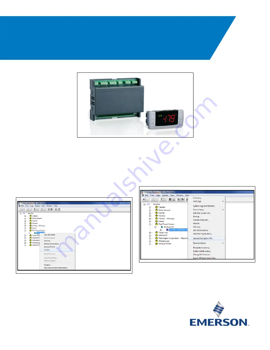
1. Connect to the E2 controller using UltraSite 

Software.

2. Open UltraSite and proceed to the created 

site with the communications information of 

the controller. Right click the site and click 

Connect

.

3. Once logged in and connected, right click the 

E2 controller icon and select 

Upload 

Description File

. If there are multiple 

controllers, make sure to choose the correct 

controller. 

Figure 1  - XM670K and CX6600 Keyboard

Figure 2  - UltraSite Directory

Figure 3  - UltraSite - Upload Description File

Quick Start Guide

XM670K_50 Dual Compressor 
with E2E

Summary of Contents for XM670K 50

Page 1: ...using UltraSite Software 2 Open UltraSite and proceed to the created site with the communications information of the controller Right click the site and click Connect 3 Once logged in and connected right click the E2 controller icon and select Upload Description File If there are multiple controllers make sure to choose the correct controller Figure 1 XM670K and CX6600 Keyboard Figure 2 UltraSite ...

Page 2: ...hen reboot the controller 5 Click Browse and select the location of the description file Click Open then Upload 6 A prompt box will appear indicating that the description file has been uploaded Select OK 7 Once the description file uploading process has been competed reboot the E2 controller The description file will not be loaded into memory until the controller is rebooted Right click the contro...

Page 3: ...ense Key issued for the device If entered correctly the message License Feature Activated will appear on the screen Device Setup Setting the Address on XM670K_50 using the CX660 Keyboard 1 Press at the same time for five 5 seconds to open first level programming The display will stop flashing once it enters the programming mode 2 Navigate through parameters by pressing or until Adr appears on the ...

Page 4: ...ress to set configuration 6 Press to select options and set the MODBUS connection as follows 7 Press to set configuration and to save the changes 8 Press to return to the Home screen Note The XM670K MODBUS Connection must be set to 9600 baud Adding a XM670K_50 Controller in E2 1 Press to enter Connected I O Boards and Controllers 2 Press once to move to C4 Third Party tab Highlight the XM670K_50 a...

Page 5: ...nd press Note The MODBUS device address chosen here must be the same as the address assigned on the device 4 The prompt box below will appear then press to continue 5 Press to save the assigned address and press to return to the Home screen 6 Press to enter the Network Summary screen Wait for 30 60 seconds and the XM670K_50 should appear Online 7 Repeat the process for other devices Adding a Stand...

Page 6: ...wn and select Standard Circuit 4 Press to confirm Scroll down to the How many field and type the desired amount of Standard Circuits required 5 Press to confirm A prompt box will appear Press Y to edit the new application 6 Rename the Standard Circuit to the desired name Press to confirm and save changes 7 Press to return to the Home screen Figure 18 Add Application Figure 19 Select Application Ty...

Page 7: ...he latest technical documentation and updates Connecting XM670K_50 to a Standard Circuit 1 From the Home screen press for Circuits 2 Highlight the Standard Circuit you wish to edit 3 Press SETUP 4 Rename the Standard Circuit if not yet renamed Figure 22 Main Menu Standard Circuits Figure 23 Summary Standard Circuits Figure 24 General Tab Standard Circuits Figure 25 Rename the Standard Circuit ...

Page 8: ...ust match the device defrost settings 8 In the Defrost tab select the property Term Type Press LOOK UP and choose THERMOSTAT 9 This will expose a digital input in the Inputs tab to route the XM670K_50 Device Application property DEFROST END which will be the standard circuit indication to terminate the circuit defrost updating the circuit status 10 Press to advance to the Defr Times tab and set th...

Page 9: ...cal documentation and updates 12 13 Press for Configured Applications 14 Highlight and choose XM670K_50 15 Choose the XM670K_50 to edit and connect to the Standard Circuit that was set up above 16 Press SETUP and rename the device Figure 30 Defr Start Mod Standard Circuits Figure 31 Configured Applications Figure 32 Configured Applications XM670K_50 Figure 33 Summary XM670K_50 Figure 34 General Ta...

Page 10: ...Alternate I O Formats 19 Choose to convert this input to a pointer from a fixed value 20 Once converted to a pointer the input will look like this 21 With Area Ctrl highlighted press LOOKUP and select the controller Using the right arrow key go to Application and press LOOKUP and select the circuit 22 Using the right arrow key go to Output and press LOOKUP and select the ACTIVE SETPOINT property o...

Page 11: ...e 40 25 The Defrost Start property would be the input pointed to from the Defrost Output property from the Standard Circuit 26 Advance to the Outputs tab Only two properties will be pointed back to the Standard Circuit as shown in Figure 42 NOTE If the Standard Circuit Defrost Term Type property was not set to Thermostat the available DEFR DV TERM 1 will not display while executing LOOKUP REVIEW T...

Page 12: ...provides temperature setpoint and does not control refrigeration 1 Each E2 property in the XM670K_50 has property help to aid in understanding Highlight a property and press the to get more details 2 When one or more settings are changed in the Setup tab go back to the Main Status screen of the XM670K_50 and press 3 Select Application Commands and press Then choose Send E2 Cfg to Device In this wa...

Page 13: ...art up All defrost settings will be obeyed during this defrost and all defrosts after if not connected to a supervisory controller that is commanding defrost via a schedule This has to be set to YES for the device to have a first defrost in order for the device to begin its internal time count for parameter DEFR INTERVAL idF Display Delay dLy Display update rate Sets local temperature update rate ...

Page 14: ... configured TMP2 ALRM PROBE rA2 TMP2 ALRM HYST A2H sets the temperature that is subtracted from the TMP2 ALARM HI A2U or added to TMP2 ALRM PROBE rA2 This setting is not influenced by how TEMP ALRM CFG ALC is set TMP2 Alarm settings are only Absolute Example TMP2 ALARM HI A2U set at 50 TMP2 ALRM HYST A2H set at 2 Alarm will go on at 50 degrees or above and alarm would be off at 48 degrees and belo...

Page 15: ...or open alarm status Reports as ON if either Digital Input 1 Digital Input 2 or Digital Input 3 is configured for the Door Switch and after the respective digital input delay setting exceeded its time setting This alarm will show as ON in the device application Status screen in the General Status box The state of this digital output can be pointed to other E2 applications The local display will fl...

Page 16: ... selected the refrigeration relay will remain on Defr St Delay dSd Defrost Start Delay Sets the delay to start a defrost if E2 property DEFROST MODE Edf set to Interval and E2 property DEFR INTERVAL idf set to1 hour or more 0 disabled Fan During Defr FnC Fan operating mode during defrost Sets the behavior of the fan relay output during defrost Fan Delay Defr Fnd Fan delay after defrost Sets the be...

Page 17: ...et point Sets the defrost termination setpoint for the configured defrost termination sensor set at E2 property DEFR TERM PROBE dPA Defr Drip Time Fdt Defrost Drip Time Sets the defrost drip time after defrost ends 0 disabled DI 1 Polarity i1P Digital input 1 polarity CL The input is activated by closing the contact OP The input is activated by opening the contact CP1 Safety Pol i4P Digital input ...

Page 18: ...ing used to adjust possible offset of probe 2 Probe 3 Config P3C Probe 3 configuration Selects the type of probe used for probe 2 Probe 3 Offset OF3 P3 calibration Setting used to adjust possible offset of probe 3 Probe 4 Config P4C Probe 4 configuration Selects the type of probe used for probe 3 Probe 4 Offset OF4 P4 calibration Setting used to adjust possible offset of probe 4 DI 1 Delay d1d Inp...

Page 19: ...puts tab has to be mapped pointed as an input from the same application and its respective digital input 3 output property in the Outputs tab DI 3 Delay d3d Input delay or alarm delay Sets delay of activation for the input configured LIGHTS ON Command input of lights on Defaulted to fixed value of ON This can be configured to use a pointer in from another E2 application digital value output into t...

Page 20: ... temperature Reports temperature probe 3 status on application status screen Update rate 10 30 seconds Can be pointed out for use in other applications Logging set by default User can disable logging PROBE 4 TEMP dP4 Probe 4 temperature Reports temperature probe 4 status on application Status screen Update rate 10 30 seconds Can be pointed out for use in other applications Logging set by default U...

Page 21: ... output status on application Status screen Update rate 10 30 seconds Can be pointed out for use in other applications Logging set by default User can disable logging CASE TEMP Reports status of cfg regulation probe Reports device status on application Status screen Update rate 10 30 seconds Can be pointed out for use in other applications Logging set by default User can disable logging DEV STATUS...

Page 22: ...019 Emerson Climate Technologies Retail Solutions Inc This document may be photocopied for personal use Visit our website at http www emerson com for the latest technical documentation and updates Wiring Figure 46 XM670_50 Dual Compressor Wiring ...

Page 23: ...All rights reserved Document Part 026 4275 Rev 0 Page 23 of 23 Door Switch use with Walk in Box with XM670K_50 Walk In Door Switch to be wired as digital input to DI1 DI2 0r DI3 on XM670K_50 See Figure 47 Door Alarm will depend on which digital input is configured for the door switch Any of the 3 digital inputs can be used Depending on which digital input is used the digital input configuration DI...

Reviews: