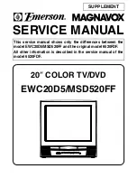
background image

SERVICE MANUAL

This service manual shows only the differences between the
model EWC20D5/MSD520FF and the original model 6520FDF.
All other information is described in the service manual of the
model 6520FDF.

20

 COLOR TV/DVD

EWC20D5/MSD520FF

L

K

L

K

C

H

B

A

G

F

SUPPLEMENT

Summary of Contents for Magnavox EWC20D5

Page 1: ... shows only the differences between the model EWC20D5 MSD520FF and the original model 6520FDF All other information is described in the service manual of the model 6520FDF 20 COLOR TV DVD EWC20D5 MSD520FF L K L K C H B A G F SUPPLEMENT ...

Page 2: ...101UB S5 LABEL EAS H3761UD MAKER NO ZLLFNSLE1 X2 OWNERS MANUAL T9101UB 1EMN20432 X3 REMOTE CONTROL 182 ERC001 NE208UD NE208UD Ref No Description Part No MECHANICAL PARTS A1X FRONT CABINET ASSEMBLY T9108UJ 1EM120250 A1 1 FRONT CABINET T9108UJ 1EM120254 A1 2 CONTROL PLATE T9108UJ 1EM320315 A1 3 BRAND BADGE B7304UE MAGNABOX 0EM401476 A3 RATING LABEL T9108UJ A4 Not Used A5 TRAY PANEL T9103UD 1EM420852...

Page 3: ...SERVICE MANUAL 20 COLOR TV DVD Sec 1 Main Section I Specifications I Adjustment Procedures I Schematic Diagrams I CBA s Sec 2 Exploded views and Parts List Section I Exploded views I Parts List 6520FDD ...

Page 4: ...roper ser vice methods may damage the equipment It also is important to understand that these CAUTIONS and NOTICES ARE NOT EXHAUSTIVE Funai could not possibly know evaluate and advice the service trade of all conceivable ways in which service might be done or of the possible hazardous consequences of each way Consequently Funai has not undertaken any such broad evalua tion Accordingly a servicer w...

Page 5: ...unctions 1 5 1 Cabinet Disassembly Instructions 1 6 1 Electrical Adjustment Instructions 1 7 1 FIRMWARE Renewal Mode 1 8 1 Block Diagrams 1 9 1 Schematic Diagrams CBA s and Test Points 1 10 1 Waveforms 1 11 1 Wiring Diagrams 1 12 1 System Control Timing Charts 1 13 1 IC Pin Functions 1 14 1 Lead Identifications 1 15 1 Sec 1 Main Section I Specifications I Adjustment Procedures I Schematic Diagrams...

Page 6: ...e worst condition that still might be considered acceptable In no case should a unit fail to meet limit specifica tions Description Condition Unit Nominal Limit 1 Over Scan 90 2 Linearity Horizontal 15 Vertical 10 3 High Voltage kV 27 Description Condition Unit Nominal Limit 1 Misconvergence Center m m 0 4 Corner m m 2 1 Side m m 1 4 2 Tint Control Range deg 30 3 Contrast Control Range dB 6 2 4 Br...

Page 7: ... All Items are measured without pre emphasis unless otherwise specified 2 Power supply AC120 V 60 Hz 3 Load imp 100 K ohm 4 Room ambient temperature 25 C ITEM CONDITIONS UNIT NOMINAL LIMIT 1 Coaxial Digital Out 75 ohm load mVpp 500 100 ...

Page 8: ...tion shown in the figure When checking the laser diode be sure to keep your eyes at least 30cm away from the pickup lens when the diode is turned on Do not look directly at the laser beam Caution Use of controls and adjustments or doing procedures other than those specified herein may result in hazardous radiation exposure Do not look directly at the laser beam coming from the pickup or allow it t...

Page 9: ...rongs tied together and touch the other ohmme ter lead in turn to each tuner antenna input ex posed terminal screw and if applicable to the coaxial connector If the measured resistance is less than 1 0 megohm or greater than 5 2 mego hm an abnormality exists that must be corrected before the instrument is returned to the customer Repeat this test with the instrument AC switch in the off position d...

Page 10: ...ted to the ground side of the AC power source To confirm that the AC power plug is inserted correctly with an AC volt meter measure between the chassis and a known earth ground If a voltage reading in excess of 1 0V is obtained remove and reinsert the AC power plug in the opposite polarity and again measure the voltage potential between the chassis and a known earth ground b Some TV receiver chass...

Page 11: ...not contact sharp edged or pointed parts H When a power cord has been replaced check that 5 6 kg of force in any direction will not loosen it I Also check areas surrounding repaired locations J Be careful that foreign objects screws solder droplets etc do not remain inside the set K Crimp type wire connector When replacing the power transformer in sets where the connections between the power cord ...

Page 12: ...er cord plug prongs and externally exposed accessible parts RF terminals antenna terminals video and audio input and output terminals microphone jacks earphone jacks etc Measuring Method Power ON Insert load Z between B earth ground power cord plug prongs and exposed accessible parts Use an AC voltmeter to measure across both terminals of load Z See Fig 2 and following table Table 2 Leakage curren...

Page 13: ...r With Soldering Iron a Using desoldering braid remove the solder from all pins of the Flat Pack IC When you use solder flux which is applied to all pins of the Flat Pack IC you can remove it easily Fig S 1 3 b Lift each lead of the Flat Pack IC upward one by one using a sharp pin or wire to which solder will not adhere iron wire When heating the pins use a fine tip soldering iron or a hot air Des...

Page 14: ...older all pins of the Flat Pack IC Make sure that none of the pins have solder bridges Fig S 1 1 Hot air Flat Pack IC Desoldering Machine CBA Flat Pack IC Tweezers Masking Tape Fig S 1 2 Flat Pack IC Desoldering Braid Soldering Iron Fig S 1 3 Fine Tip Soldering Iron Sharp Pin Fig S 1 4 To Solid Mounting Point Soldering Iron Iron Wire or Hot Air Blower Fig S 1 5 Example Pin 1 of the Flat Pack IC is...

Page 15: ... static electricity that may be charged on the body Ground for Work Bench Be sure to place a conductive sheet or copper plate with proper grounding 1MΩ on the work bench or other surface where the semiconductors are to be placed Because the static electricity charge on the clothing will not escape through the body grounding band be careful to avoid contacting semiconductors to clothing Presolder C...

Page 16: ...e a single digit chan nel 100 Button Press to select cable channels which are equal or greater than number 100 DVD Mode Press to enter the desired number 10 Button Press to enter the desired numbers which are equal or greater than number 10 C H A N N E L S TO P S K I P P L AY S K I P PAU S E O P E N C L O S E VO L U M E P OW E R AU D I O R L VIDEO SERCH HEADPHONE 7 4 2 8 910111213 14 6 5 3 1 26 27...

Page 17: ...ou press this button 0 30 60 90 or 120 minutes 18 REV h Button Press to view the DVD picture in fast reverse motion Press PAUSE then press this button to begin slow motion playback Press this button repeatedly to change the reverse speed of slow motion FWD g Button Press to fast forward the Disc Press PAUSE then press this button to begin slow motion playback Press this button repeatedly to change...

Page 18: ...T Ground Wire before removing the Anode Cap 1 Disconnect the following Anode Cap CN1801 CN1802 CN505 CRT CBA CN1601 and CN1571 Then remove Tray Chassis Unit CAUTION 2 Electrostatic breakdown of the laser diode in the optical system block may occur as a potential difference caused by electrostatic charge accumulated on cloth human body etc during unpacking or repair work To avoid damage of pickup f...

Page 19: ...1 6 2 TD810DC Fig 1 S 1 S 1 S 2 S 2 S 1 S 1 1 REAR CABINET Fig 2 3 CRT S 3 S 3 S 3 S 3 Anode Cap CRT CBA ...

Page 20: ...1 6 3 TD810DC Fig 3 6 Main CBA 4 DVD Mechanism 5 DVD Main CBA Unit Loder Cover Shield Box 2 Tray Chassis Unit S 4 S 4 S 6 CN301 CN201 S 5 S 5 S 7 S 7 S 7 S 7 S 7 CN002 CN001 S 8 ...

Page 21: ...1 6 4 TD810DC Fig 4 DVD Mechanism View for B Pickup Unit C B Short the three short lands by soldering Short the three short lands by soldering FPC Cable Connector Slide View for C View for A OR A ...

Page 22: ...5 TD810DC Fig 5 SCREEN FOCUS CN501 CL501A CL502A CRT CBA DVD MAIN CBA UNIT CN002 CN001 CN1802 CN1601 CN1801 CL502B CL501B CN1571 T1571 AC CORD CN201 CN301 CN601 CN401 MAIN CBA ANODE CRT GND SPEAKER SPEAKER ...

Page 23: ... service remote control unit 2 Turn the power on 3 Press DISC MENU button on the service remote control unit 1 DC 114V B Adjustment Purpose To obtain correct operation Symptom of Misadjustment The picture is dark and unit does not operate correctly Note J2023 B TP1303 GND VR1601 Main CBA 1 Connect the unit to AC Power Outlet 2 Connect DC Volt Meter to J2023 B and TP1303 GND 3 Adjust VR1601 so that...

Page 24: ...al height of screen image Symptom of Misadjustment If V Size is incorrect vertical height of image on the screen may not be properly displayed 1 Operate the unit for at least 20 minutes 2 Enter the Service mode See page 1 7 1 Press 9 button on the remote control unit and select V S Mode Press 9 button then display will change to V P and V S 3 Input monoscope pattern 4 Press CH o p buttons on the r...

Page 25: ...MA mode and after zero point calibration bring the optical recep tor to the center on the tube surface CRT 5 Enter the Service mode Press VOL p button on the service remote control unit and select C D mode Display changes C D 7F DVD KEY and DVD TEST cyclically when VOL p button is pressed 6 Press 4 button on the service remote control unit for Red adjustment Press 5 button on the service remote co...

Page 26: ...visible See above figure 3 Turn the power off and on again using the main power button on the TV unit 9 Focus Adjustment Purpose Set the optimum Focus Symptom of Misadjustment If Focus Adjustment is incorrect blurred images are shown on the display Note Focus VR FBT Main CBA FBT Fly Back Transformer 1 Operate the unit more than 30 minutes 2 Face the unit to the East and degauss the CRT us ing a de...

Page 27: ...tortion will appear on the screen Note R1583 Main CBA Use Service remote control unit 1 Connect Frequency Counter to R1583 and ground 2 Set the unit to the VIDEO mode which is located be fore CH2 and no input is necessary Enter the Ser vice mode See page 1 7 1 3 Operate the unit for at least 20 minutes 4 Press 2 button on the Service remote control unit and select H ADJ Mode 5 Press CH o p button ...

Page 28: ...mote control unit and select C D mode Display changes C D 7F DVD KEY and DVD TEST cyclically when VOL p button is pressed then press 1 The display will momentarily show CUT OFF R R Red Now there should be a horizontal line across the center of the picture tube If needed grad ually turn the screen control on the flyback clock wise until the horizontal line appears Adjust the Red Cut off by pressing...

Page 29: ...ent Purpose To obtain proper convergence of red green and blue beams Symptom of Misadjustment If Convergence Adjust ment is incorrect the edge of white letters may have color edges 1 Set the unit to the AUX Mode which is located before CH2 then input a Dot or crosshatch pattern 2 Loosen the Ring Lock and align red with blue dots or Crosshatch at the center of the screen by rotat ing RB C P Magnets...

Page 30: ...let Then plug it again 7 Turn the power on by pressing the power button and the tray will close 8 Press 1 2 3 4 and DISPLAY buttons on the remote control unit in that order Fig d appears on the screen 9 Press 3 button on the remote control unit Fig e appears on the screen 10 To finish this mode press POWER button F W Version Up Mode Please insert a DISC for F W Version Up EXIT SELECT Fig a Version...

Page 31: ...NTROL BLOCK DVD SECTION CN401 FROM TO AUDIO BLOCK P ON H CN001 Q1622 P DOWN Q1285 DVD L KEY 1 KEY 0 REMOTE RS1201 IC1202 MEMORY SCL 6 SDA 5 MAIN CBA TV MICON VIDEO CHROMA DEFLECTION 55 76 SP MUTE 79 VOLUME SP MUTE VOLUME 62 DVD MUTE DVD MUTE 65 78 59 60 61 64 12 67 66 70 7 CS 57 I2C OPEN RESET CS 10 SDATA 12 SCLK 13 REMOTE 14 Q1621 Q1623 DVD MAIN POWER DVD MAIN POWER 77 AMP STANBY AMP STANBY 63 69...

Page 32: ...7 WF18 CN002 DVD Y 1 DVD C 3 TP1733 DVD Y J1734 DVD C TP1301 VIDEO OUT FROM DIGITAL SIGNAL PROCESS BLOCK DVD SECTION CN601 CF1031 CF1032 VCO F B IC1001 IF SIGNAL PROCESS SAW FILTER VIF AMP VIDEO DET VCO 4 5MHz FILTER LPF IF AGC DET EQ AMP RF AGC AMP AFT 4 5MHz TRAP FM DET 20 14 16 22 7 21 5 3 8 1 11 TU1001 SF1001 IF AGC SDA SCL EXT CLK 1 11 5 4 8 17 TU AUDIO WF16 WF1 TO AUDIO BLOCK AFT TO SYSTEM C...

Page 33: ... SELECT SW CTL 14 15 12 13 2 1 10 11 TUNER TUNER LINE LINE L CH R CH Q1454 SPDIF 10 DVD AUDIO R 8 DVD AUDIO L 7 DVD A MUTE 6 FROM DVD AUDIO BLOCK DVD SECTION CN601 TO SYSTEM CONTROL BLOCK CN002 AUDIO R IN JK1702 Q1736 AUDIO L IN JK1703 WF19 WF20 14 IC1801 AUDIO AMP 7 VOLUME 11 6 AMP AMP MUTE STANDBY CONTROL 8 1 3 TUNER LINE TUNER LINE DVD DVD L CH R CH 2 12 VOLUME CONTROL Q1282 SP MUTE DVD L TP140...

Page 34: ...HEATER ANODE GND V501 CRT GND FOCUS SCREEN JK501 HEATER 3 3 CN501 CL501A CL501B VIDEO SIGNAL TUNER LINE CN1571 160V 1 1 FROM TO IF VIDEO BLOCK 11 S F HV FOCUS VR SCREEN VR 1 9 8 1 9 7 FROM POWER SUPPLY BLOCK H OUTPUT 1 3 5 4 5 4 3 1 WF8 WF7 WF14 WF15 WF13 WF10 WF11 WF9 WF12 RED AMP WF3 WF4 WF5 DVD VIDEO SIGNAL 4 4 RED 3 3 GREEN 2 2 BLUE ACL H DRIVE AFC V DRIVE V RAMP F B BLUE GREEN RED DEF B B TP1...

Page 35: ...nts in the power supply circuit are not defective before you connect the AC plug to the AC power supply Otherwise it may cause some components in the power supply circuit to fail P ON 12V P ON 8V P ON 5V 2 5V SWITCHING Q1616 SWITCHING Q1606 Q1607 Q1612 1 5V REGULATOR IC1602 DVD MAIN POWER FROM PIN77 OF IC1201 P ON H FROM PIN78 OF IC1201 BACK UP P DOWN CN001 CN401 AUDIO 5V TO SYSTEM CONTROL BLOCK E...

Page 36: ...C 36 864MHz OSC SPINDLE MOTOR DRIVE TRACKING ACTUATOR DRIVE EXT CLOCK CLK33M BE CLOCK 172 170 150 TRAY OUT TRAY IN FG IN 97 SLD 70 SPDL 71 TRACKING DRIVE 152 FOCUS DRIVE 60 66 TO DIGITAL SIGNAL PROCESS BLOCK DIAGRAM FS FS TS TS TO DVD AUDIO BLOCK DIAGRAM 51 ADAC MD 50 ADAC MC 96 ADAC ML ADAC MC ADAC ML PCM SCLK 95 A MUTE ADAC MD A MUTE 17 92 FSEL RESET 68 RESET IC461 5 4 3 3V TRAY OUT TRAY IN FOCU...

Page 37: ...ST ROM DATA ROM INST ROM SERIAL D A GENERAL I O INTERRUPT CONTROLLER TIMER WATCH DOG TIMER 32BIT CPU STREAM I F EXTERNAL MEMORY I F SDRAM ECC UMAC 124 125 122 123 128 129 126 127 131 130 135 133 132 134 78 DEBUG BCU INST CACHE D TYPE LATCH DATA CACHE D A TO IF VIDEO BLOCK TV SECTION CN002 158 164 Y CN601 C TO DVD AUDIO BLOCK DIAGRAM 181 SPDIF 175 PCM BCK 176 PCM DATA0 174 PCM LRCLK EXADT 0 15 EXAD...

Page 38: ...SERIAL PORT SERIAL CONTROL 4X 8X OVERSAMPLING DIGITAL FILTER FUNCTION CONTROLLER ENHANCED MULTI LEVEL DELTA SIGMA MODULATOR DAC LPF AMP L CH R CH LPF AMP DAC SYSTEM CLOCK PCM BCK SPDIF PCM DATA0 PCM LRCLK ADAC MD ADAC MC ADAC ML PCM SCLK DVD MAIN CBA UNIT DATA AUDIO SIGNAL A MUTE 10 SPDIF 7 DVD AUDIO L 8 DVD AUDIO R 6 DVD A MUTE TO AUDIO BLOCK TV SECTION CN002 DVD AUDIO SIGNAL ...

Page 39: ... identified by the mark in the schematic diagram and the parts list Before replacing any of these components read the parts list in this manual carefully The use of substitute replacement parts that do not have the same safety characteristics as speci fied in the parts list may create shock fire or other hazards Capacitor Temperature Markings Capacitors and transistors are represented by the fol l...

Page 40: ...he parts list section of the service manual 4 Wire Connectors 1 Prefix symbol CN means connector can disconnect and reconnect 2 Prefix symbol CL means wire solder holes of the PCB wire is soldered directly 5 Mode SP REC 6 Voltage indications on the schematics are as shown below Plug the TV power cord into a standard AC outlet 7 How to read converged lines 8 Test Point Information 2 3 1 5 0 2 5 0 T...

Page 41: ... VIDEO SIGNAL DVD VIDEO SIGNAL Main 1 6 Schematic Diagram TV Section 1 10 3 1 10 4 TD810SCM1 MAIN 1 6 Ref No Position IC1201 B 2 Q1285 B 1 Q1301 D 1 Q1303 D 1 Q1304 E 2 Q1305 D 4 Q1306 E 3 Q1307 E 3 Q1308 E 3 TP1301 D 1 TP1303 E 1 TP1304 E 4 TP1305 E 4 TP1501 E 4 TP1502 E 4 TP1503 F 4 TEST POINTS IC TRANSISTORS ...

Page 42: ...K2 K3 K4 L1 L2 L3 L4 VIDEO TV LINE SIGNAL AUDIO TV LINE SIGNAL 1 10 5 1 10 6 TD810SCM2 Main 2 6 Schematic Diagram TV Section MAIN 2 6 Ref No Position IC1001 J 3 IC1202 J 3 IC1452 H 1 Q1454 I 1 TP1401 I 2 TP1402 I 2 TP1731 I 2 ICS TRANSISTOR TEST POINTS ...

Page 43: ...AL AUDIO TV LINE SIGNAL DATA AUDIO SIGNAL 1 10 7 1 10 8 TD810SCM3 Main 3 6 Schematic Diagram TV Section MAIN 3 6 Ref No Position IC1801 O 3 Q1282 N 2 Q1731 Q 3 Q1736 M 1 CN002 R 2 CN1801 M 3 CN1802 M 4 J1734 O 1 TP1403 P 2 TP1404 P 2 TP1405 O 3 TP1732 Q 3 TP1733 O 1 IC TRANSISTORS CONNECTORS TEST POINTS ...

Page 44: ...TYPE DE 4A 125V 4A 125V CAUTION Fixed voltage or Auto voltage selectable power supply circuit is used in this unit If Main Fuse F1601 is blown check to see that all components in the power supply circuit are not defective before you connect the AC plug to the AC power supply Otherwise it may cause some components in the power supply circuit to fail MAIN 4 6 Ref No Position IC1601 T 2 Q1601 S 2 Q16...

Page 45: ... BB2 BB3 CC1 CC2 CC3 1 10 11 1 10 12 TD810SCM5 Main 5 6 Schematic Diagram TV Section MAIN 5 6 Ref No Position IC1602 Z 2 IC1603 AA 3 IC1604 Z 3 Q1615 BB 3 Q1619 Z 3 Q1621 BB 2 Q1622 BB 2 Q1623 AA 1 CN001 CC 3 ICS TRANSISTORS CONNECTORS ...

Page 46: ...14 TD810SCM6 Main 6 6 CRT Schematic Diagram TV Section MAIN 6 6 Ref No Position IC1551 DD 3 Q1571 FF 2 Q1572 EE 3 Q1591 EE 2 CL501B GG 2 CL502B GG 2 CN1571 EE 3 J2023 FF 2 TRANSISTORS CONNECTORS TEST POINTS IC CRT Ref No Position Q511 HH 2 Q521 HH 2 Q531 HH 2 CN501 II 1 CL501A GG 2 CL502A GG 2 CONNECTORS TRANSISTORS ...

Page 47: ...EO AUDIO TRACKING SERVO SIGNAL SPINDLE SERVO SIGNAL SLED SERVO SIGNAL 1 10 15 1 10 16 TD810SCD1 DVD Main 1 3 Schematic Diagram DVD Section DVD MAIN 1 3 Ref No Position IC201 B 1 IC202 E 4 IC301 D 3 IC461 E 1 Q251 C 2 Q252 B 2 Q253 C 2 Q254 B 2 CN201 A 3 CN301 A 1 CN401 F 2 CONNECTORS ICS TRANSISTORS ...

Page 48: ... K4 L1 L2 L3 L4 DVD VIDEO SIGNAL DATA VIDEO AUDIO SPINDLE SERVO SIGNAL SLED SERVO SIGNAL FOCUS SERVO SIGNAL TRACKING SERVO SIGNAL DATA AUDIO SIGNAL 1 10 17 1 10 18 TD810SCD2 DVD Main 2 3 Schematic Diagram DVD Section DVD MAIN 2 3 Ref No Position IC101 H 4 IC ...

Page 49: ... 3 3 3 155 0 0 187 219 251 156 2 2 2 2 188 220 252 157 3 3 3 3 189 3 3 3 3 221 0 0 253 158 0 7 0 7 190 222 1 5 1 5 254 0 0 159 0 0 191 223 1 9 1 9 255 160 192 224 0 0 256 IC101 VOLTAGE CHART PIN NO PLAY STOP PIN NO PLAY STOP PIN NO PLAY STOP PIN NO PLAY STOP 1 3 3 3 3 33 2 2 2 9 65 0 1 0 1 97 3 4 3 4 2 34 66 1 2 2 5 98 1 6 1 6 3 35 67 1 6 1 6 99 0 0 4 0 0 36 68 3 4 3 4 100 5 37 69 0 0 101 6 38 0 3...

Page 50: ...2 Q3 Q4 R1 R2 R3 R4 DVD AUDIO SIGNAL DVD VIDEO SIGNAL DATA AUDIO SIGNAL 1 10 21 1 10 22 TD810SCD3 DVD Main 3 3 Schematic Diagram DVD Section DVD MAIN 3 3 Ref No Position IC102 O 4 IC103 O 3 IC104 N 3 IC105 N 1 IC451 P 3 IC601 Q 1 CN601 R 1 ICS CONNECTOR ...

Page 51: ...n check to see that all components in the power supply circuit are not defective before you connect the AC plug to the AC power supply Otherwise it may cause some components in the power supply circuit to fail MAIN CBA Ref No Position Ref No Position IC1001 D 4 Q1616 C 2 IC1201 B 3 Q1619 D 2 IC1202 A 2 Q1621 C 3 IC1452 A 4 Q1622 C 4 IC1551 D 1 Q1623 C 3 IC1601 E 3 Q1731 B 4 IC1602 D 3 Q1736 B 4 IC...

Page 52: ...TROUBLESHOOTING THIS TYPE POWER SUPPLY CIRCUIT A VARIABLE ISOLATION TRANSFORMER IS REQUIRED NOTE The voltage for parts in hot circuit is measured using hot GND as a common terminal CAUTION FOR CONTINUED PROTECTION AGAINST RISK OF FIRE REPLACE ONLY WITH SAME TYPE 4A 125V FUSE ATTENTION UTILISER UN FUSIBLE DE RECHANGE DE MÊME TYPE DE 4A 125V 4A 125V 1 10 25 BTD810F01011 CAUTION Fixed voltage or Auto...

Page 53: ...lector Q521 Base WF4 WF13 Q531 Collector Q531 Base WF5 1 10 27 1 10 28 CRT CBA Top View TV Section CRT CBA Bottom View TV Section BTD810F01011 CRT CBA Ref No Position Q511 A 2 Q521 A 2 Q531 B 2 CN501 B 1 CL501A B 2 CL502A A 2 CONNECTORS TRANSISTORS ...

Page 54: ...V 20µsec Q1571 Base WF8 1DIV 20V 20µsec Q531 Collector WF13 1DIV 0 2V 20µsec CN002 Pin 1 WF17 1DIV 20V 20µsec Q511 Collector WF15 1DIV 1V 0 5msec CN002 Pin 7 WF19 1DIV 1V 0 1µsec CN002 Pin 10 WF20 1DIV 0 2V 20µsec TU1001 Pin 8 WF16 GND TD810WF WF1 WF20 Waveforms to be observed at Waveform check points Shown in Schematic Diagram Input NTSC Color Bar Signal with 1kHz Audio Signal WF1 WF16 DVD Video ...

Page 55: ...7 DVD AUDIO R 8 8 AUDIO 5V 9 9 FS TS DETECTOR 11 2 3 5 6 4 7 FG CBA FG SENSOR TRAY OUT SW3001 SW3002 M SLED MOTOR M SPINDLE MOTOR 1 GND 2 E 3 DVD ON 5V 4 VREF 5 B 6 C 7 D 8 A 9 CD DVD 10 F 11 GND LD 12 CD LD 13 PD MONI 14 DVD LD 15 GND DVD PD 16 GND CD PD 17 TS 18 FS 19 FS 20 TS FOCUS SCREEN GND D Y HD VD CN501 CLN551 CN1601 CL501B CL502B T1571 FBT CRT 1 2 3 4 5 CN1571 ANODE CL501A CL502A 4 RED 3 ...

Page 56: ...Tray IN TL221 3 3V 0V 0V 3 3V 0V 1 65V 0V 0V 0V 1 65V 1 65V 1 65V Tray OUT TL220 Sled Drive TP303 Disc Drive TP301 Focus Drive TP304 Tracking Drive Tracking Drive TP302 Tray Close Disc Rotation Play Disc Stop Tray Open SYSTEM CONTROL TIMING CHARTS ...

Page 57: ...k Output 3 58MHz 33 N U Not Used 34 N U Not Used 35 N U Not Used 36 N U Not Used 37 V RAMP F B V Ramp Feed Back 38 V RAMP OUT Vertical Output 39 V RAMP CAP V Ramp OSC Capacitor 40 N U Not Used 41 N U Not Used 42 H VCO F B H Vco Feed Back 43 AFC FILT Horizontal AFC Filter 44 GND GND 45 FBP IN Flyback Pulse Input 46 H OUT H Pulse Output 47 VCC Vcc 48 VCC Vcc 49 VCC Vcc 50 R OUT Red Output 51 G OUT G...

Page 58: ...ountermeasure 73 P SAFETY 1 Power Supply Protection 74 P SAFETY 2 Power Supply Protection 75 P SAFETY 3 Power Supply Protection 76 EXT L Switching External Input 77 DVD MAIN POWER Power On Signal to High for DVD 78 P ON H Output for P ON H 79 SP MUTE Speaker Mute Output 80 ACL CONT ACL Control Signal Pin No Signal Name Function ...

Page 59: ...SZ 1 2 3 4 1 Vin 2 Vo 3 GND 4 Vc R A K KIA431 AT E C B 2SC3400 KTA1266 GR BN1F4M T KTC3199 BR 2SC2785 J H F KRC103M KRA103M BA1F4M T 2SA950 Y O KTA1271 Y 2SA1175 F KTA1267 GR 2SA1015 GR TPE2 2SC2120 O Y TPE2 2SC1815 GR TPE2 KTC3198 GR 2SC1627Y TPE2 KTC3203 Y KTC2804 Y KTC3199 GR E C B 3 2 4 1 PS2501 1W PS2501 1L Note A Anode K Cathode E Emitter C Collector B Base R Reference S Source G Gate D Drai...

Page 60: ...TION 20 COLOR TV DVD 6520FDD TABLE OF CONTENTS Cabinet Exploded Views 2 1 1 Packing Exploded Views 2 1 3 Mechanical Parts List 2 2 1 Electrical Parts List 2 3 1 Sec 2 Exploded views and Parts List Section I Exploded views I Parts List ...

Page 61: ...3 TB12 B2 B2 V501 B2 B2 B1 B4 B4 B4 B4 A4 L4 L4 CL2801 SP2801 B6 A1X L4 L4 B6 TB6 V501 1 L551 Details for L551 and surrounding parts SHINWHA TAPE SGT 730 WHITE SHINWHA TAPE SGT 730 BLACK V501 3 V501 2 SCOTCH TAPE 880 SCOTCH TAPE 880 DG601 CLN551 CRT CBA Main CBA DVD Main CBA Unit CL1802 SP1802 1B1 W1601 EXPLODED VIEWS Cabinet 2 1 1 2 1 2 TD810CEX ...

Page 62: ...FRONT PACKING TAPE S1 S3 S6 S14 X3 X4 X2 X7 X1 TAPE PACKING TAPE PACKING TAPE S2 PACKING TAPE PACKING TAPE S4 Packing 2 1 3 TD810PEX ...

Page 63: ... 053 LLBH00ZTM053 L1 SCREW P TIGHT 4X18 BIND HEAD GBMP4180 L2 SCREW TAPPING M4X14 DBU14140 L4 SCREW ASSEMBLED 12 M3X12 0EM406746 L7 SCREW P TIGHT 3X10 BIND HEAD GBKP3100 SP1802 SPEAKER S08F02B or DSD0808XQ010 SPEAKER J F097 C5 DSD0808DCP01 SP2801 SPEAKER S08F02B or DSD0808XQ010 SPEAKER J F097 C5 DSD0808DCP01 TB1 TRAY CHASSIS TD810UA 0EM000801 TB2 SHIELD BOX TD808UJ 0EM301945 TB10 RCA HOLDER TD810U...

Page 64: ... CHIP CERAMIC CAP B K 1000pF 50V CHD1JKB0B102 C1206 CHIP CERAMIC CAP B K 220pF 50V CHD1JKB0B221 C1207 FILM CAP P 0 001µF 50V J or CMA1JJS00102 FILM CAP P 0 001µF 50V J CA1J102MS029 C1209 CHIP CERAMIC CAP F Z 0 1µF 25V CHD1EZB0F104 C1214 CERAMIC CAP AX Y M 0 01µF 16V CCA1CMT0Y103 C1215 CHIP CERAMIC CAP MELF F Z 0 01µF 16V CZM1CZB0F103 C1216 CHIP CERAMIC CAP MELF F Z 0 01µF 16V CZM1CZB0F103 C1217 CH...

Page 65: ...4 7µF 250V M or CE2EMASDL4R7 ELECTROLYTIC CAP 4 7µF 250V M CE2EMASTL4R7 C1577 FILM CAP P 0 022µF 50V J or CMA1JJS00223 Ref No Description Part No FILM CAP P 0 022µF 50V J CA1J223MS029 C1578 ELECTROLYTIC CAP 47µF 35V M or CE1GMASDL470 ELECTROLYTIC CAP 47µF 35V M CE1GMASTL470 C1580 P P CAP 0 01µF 1 6KV J or CA3C103VC011 PP CAP 0 01µF 1 6KV J or CT3C103MS039 METALLIZED FILM CAP 0 01µF 1 6KV J or CT3C...

Page 66: ...E1JMASDL100 ELECTROLYTIC CAP 10µF 50V M CE1JMASTL100 C1749 ELECTROLYTIC CAP 10µF 50V M or CE1JMASDL100 ELECTROLYTIC CAP 10µF 50V M CE1JMASTL100 C1758 CHIP CERAMIC CAP MELF SL J 100pF 50V CZM1JJBSL101 C1762 ELECTROLYTIC CAP 10µF 50V M or CE1JMASDL100 Ref No Description Part No ELECTROLYTIC CAP 10µF 50V M CE1JMASTL100 C1801 ELECTROLYTIC CAP 1µF 50V M or CE1JMASDL1R0 ELECTROLYTIC CAP 1µF 50V M or CE1...

Page 67: ...r QDTZ001SS133 SWITCHING DIODE 1N4148 NDTZ001N4148 Ref No Description Part No D1617 SCHOTTKY BARRIER DIODE 11EQS04 or QD4Z011EQS04 SCHOTTKY BARRIER DIODE ERA81 004 QDPZERA81004 D1618 FAST RECOVERY DIODE ERC25 06L3 QD4Z0ERC2506 D1619 DIODE FR104 B NDLZ000FR104 D1620 ZENER DIODE MTZJT 777 5B or QDTB0MTZJ7R5 ZENER DIODE DZ 7 5BSBT265 NDTB0DZ7R5BS D1621 SWITCHING DIODE 1SS133 T 77 or QDTZ001SS133 SWIT...

Page 68: ...cription Part No RES BUILT IN TRANSISTOR BN1F4M T QQSZ00BN1F4M Q1301 TRANSISTOR 2SC2785 F or QQSF02SC2785 TRANSISTOR 2SC2785 H or QQSH02SC2785 TRANSISTOR 2SC2785 J or QQSJ02SC2785 TRANSISTOR KTC3199 GR or NQS10KTC3199 TRANSISTOR KTC3198 GR or NQS40KTC3198 TRANSISTOR 2SC1815 GR TPE2 QQS102SC1815 Q1303 TRANSISTOR 2SC2120 O TPE2 or QQS002SC2120 TRANSISTOR 2SC2120 Y TPE2 or QQSY02SC2120 TRANSISTOR KTC...

Page 69: ...9 GR or NQS10KTC3199 TRANSISTOR KTC3198 GR or NQS40KTC3198 TRANSISTOR 2SC1815 GR TPE2 QQS102SC1815 RESISTORS R1001 CHIP RES 1608 1 10W J 100 Ω RRXAJB5Z0101 R1002 CHIP RES 1608 1 10W J 100 Ω RRXAJB5Z0101 R1032 CHIP RES 1608 1 10W J 100 Ω RRXAJB5Z0101 R1034 CARBON RES 1 4W J 220 Ω RCX4JATZ0221 R1037 CHIP RES 1608 1 10W J 180 Ω RRXAJB5Z0181 R1038 CARBON RES 1 4W J 180 Ω RCX4JATZ0181 R1039 CHIP RES 16...

Page 70: ...PER D0 6 P5 0 JW5 0T R1566 CARBON RES 1 4W J 2 2 Ω RCX4JATZ02R2 Ref No Description Part No R1567 CARBON RES 1 4W J 2 2 Ω RCX4JATZ02R2 R1568 CARBON RES 1 4W J 2 2k Ω RCX4JATZ0222 R1569 CARBON RES 1 4W J 39 Ω RCX4JATZ0390 R1570 CARBON RES 1 4W J 1 8 Ω RCX4JATZ01R8 R1571 CARBON RES 1 4W J 180 Ω RCX4JATZ0181 R1572 CARBON RES 1 4W J 560 Ω RCX4JATZ0561 R1573 CARBON RES 1 4W J 560 Ω RCX4JATZ0561 R1574 ME...

Page 71: ...Ω RRXAJB5Z0472 R1701 CHIP RES 1608 1 10W J 75 Ω RRXAJB5Z0750 R1702 CHIP RES 1608 1 10W J 18k Ω RRXAJB5Z0183 R1703 CHIP RES 1608 1 10W J 100k Ω RRXAJB5Z0104 Ref No Description Part No R1704 CHIP RES 1608 1 10W J 18k Ω RRXAJB5Z0183 R1706 CHIP RES 1608 1 10W J 100k Ω RRXAJB5Z0104 R1707 CHIP RES 1608 1 10W J 100 Ω RRXAJB5Z0101 R1708 CHIP RES 1608 1 10W J 100 Ω RRXAJB5Z0101 R1733 CHIP RES 1608 1 10W J ...

Page 72: ...LP2 005 LTH00CPA5005 T1601 SWITCHING TRANS 03709 LTT00CPKT111 TB4 H V HEAT SINK PHz ASSEMBLY TD810UA 0EM408434 TB5 19VPOW HEAT SINK PHB ASSEMBLYT7400UA 0EM407685 TB6 POW HEAT SINK PHY TD808UJ 0EM408428 TL2 SCREW B TIGHT M3X8 BIND HEAD GBMB3080 TP1301 PCB JUMPER D0 6 P10 0 JW10 0T TP1303 PCB JUMPER D0 6 P7 5 JW7 5T Ref No Description Part No TP1304 PCB JUMPER D0 6 P5 0 JW5 0T TP1305 PCB JUMPER D0 6...

Page 73: ...STOR 3W J 10k Ω or RN03103ZU001 FIXED METAL OXIDE FILM RES 3W J 10k Ω RN03103DP005 R521 CARBON RES 1 4W J 100 Ω RCX4JATZ0101 R522 CARBON RES 1 4W J 330 Ω RCX4JATZ0331 R523 CARBON RES 1 4W J 8 2k Ω RCX4JATZ0822 R526 CARBON RES 1 4W J 1 5k Ω RCX4JATZ0152 R527 CARBON RES 1 4W J 1 5k Ω RCX4JATZ0152 R530 METAL RESISTOR 3W J 10k Ω or RN03103ZU001 FIXED METAL OXIDE FILM RES 3W J 10k Ω RN03103DP005 R531 C...

Page 74: ...Printed in Japan 2003 10 03 HO 6520FDD TD810UA ...

Reviews: