


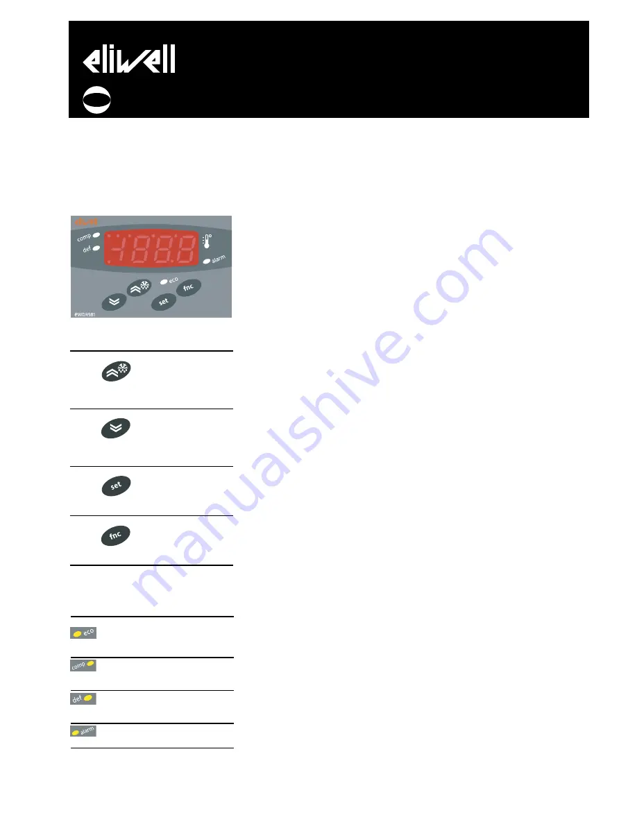
USER INTERFACE
The user interface has a 4 LED display to
indicate status and alarms and four buttons
for controlling instrument status and pro-
gramming.
KEYS
UP
Increase in value of
parameter
Menu scrolling and
activation of defrost
function
(Parameter programmable
H31)
DOWN
Decrease in value of
parameter
Menu scrolling and
activation of associated
function
(Parameter programmable
H32)
set
Access to different levels of
menu
Alarm display, set
point and probes
Access to programming of
parameters
fnc
Exit current level of
menu
Confirmation of value of para-
meter
(Parameter programmable
H33)
SIGNAL LED
The status of the external devices, functions
and controllers is described by the device
LEDs.
DISPLAY
This is used to display the inputs, the set
point, the parameters and related values,
alarms, functions and the status of the
device.
DESCRIPTION OF MENU
Access to both menus is controlled by
the ‘set’ button. If it is pressed and
immediately released, the ‘machine
status menu‘ is displayed. Hold the same
button down for 5 seconds to access the
‘parameter programming menu‘.
When one of the two menus has been
accessed, you can navigate between the
level 1 folders using the ‘UP’ and ‘DOWN’
buttons. The folders are opened by
pressing the ‘set’ button once. You can
now scroll through the contents of each
folder, modify it or use its functions.
You can exit each level of both menus in
three ways: using the ‘fnc’ button, if a
new value is confirmed by pressing the
‘set’ button or, when the time-out has
elapsed (15 seconds inactivity on the
device).
MACHINE STATUS MENU
The ‘machine status menu’ contains the
folders and basic information on the
device:
-AL: alarm folder
-SEt: Set point setting folder
-Pb1: ‘probe 1 value’ folder
-Pb3: ‘probe 3 value’ folder
If no alarms are present, the “SEt” label
is displayed. From here, you can scroll
down the other menu items using the
UP’ and ‘DOWN’ buttons.
Each folder can be accessed by pressing
the ‘set’ button once. Values are
modified using the ‘UP’ and ‘DOWN’
buttons and the ‘set’ button that
confirms the selected value and takes
you back to the higher level.
Setting the set point
Access the ‘machine status menu’. If no
alarms are present, the “SEt” label is
displayed. By pressing and immediately
releasing the ‘set’ button, the set point
value can be set using the UP’ and
‘DOWN’ buttons. Press and release the
‘set’ button again or press the ‘fnc’
button to go back to the main menu
level. The set point setting folder is also
closed when the time-out elapses.
Alarm on
If an alarm condition exists when the
Machine Status menu is accessed the
“ALfolder label appears.
PARAMETER PROGRAMMING MENU
Access the menu by pressing the ‘set’
button for at least 5 seconds.
The menu structure enables all
parameter folders to be divided into two
levels.
All the level 1 folders can be accessed
by entering the password ‘PA1’.
Scroll down the level 1 folders using the
‘UP’ and ‘DOWN’ buttons. Press and
release the ‘set’ button next to the
selected label to access the parameters.
Scroll through the labels in the folder
using the ‘UP’ and ‘DOWN’ buttons,
press ‘set’ to display the current value of
the selected parameter, use the ‘UP’ and
‘DOWN’ buttons and set the required
value by pressing ‘set’.
To access the level 2 folders in the ‘Cnf’
folder, select the ‘PA2’ label, enter the
password ‘PA2’ and confirm with the ‘set’
button. All the parameters that cannot
be changed at level 1 are in this level.
NOTE: Level 1 parameters will only be
displayed if you quit the ‘parameter
programming menu’ and repeat the
steps for manipulation of level 1
folders.
The steps to follow for manipulation of
level 2 parameters are the same as those
NOTE: It is strongly recommended
that the instrument is switched off
and on again each time parameter
configuration is changed in order to
prevent malfunctioning of the
configuration and/or ongoing timings.
PASSWORD
The passwords “PA1and “PA2” are used
to access level 1 and level 2 parameters.
To change them and assign them the
desired value, access the ‘parameter
programming menu’ in the “diS” label
folder.
The password is requested:
- PA1 when entering the ‘parameter
programming menu’;
- PA2 in the “Cnf” folder containing the
level 1 parameters.
USING COPY CARD
The Copy card function can be used to
upload and download parameter maps
of one or more of the same type of
instrument.
The accessory is connected to the device
using the special TTL serial port on the
instrument. The Copy card can be used
for the following functions:
EWDR 981
electronic controllers for refrigeration units
cod. 9IS43091
rel. 3/05
GB
LED
Description
Indication
reduced set point
Lights up when
inserted
LED set point is dis-
played, blinking
when reduced set
point is inserted
compressor LED
‘on’ with LED on.
Blinking for delay,
protection or acti-
vation blocked
defrost LED
‘on’ during defrost-
ing. Blinking when
activated manually
or by digital input
alarm LED
‘on’ if alarm is pre-
sent. Blinking for
silenced
alarm decimal point
‘on’ to indicate of
voltage when on
stand-by and dis-
play ‘off’


