


Table of Contents
1. Evaluation Kit Diagram
2. Evaluation Kit Setup
3. Evaluation Kit Features
4. Audio Test Method and Specifications
5. RF Test Method and Specifications
6. Sales and Support
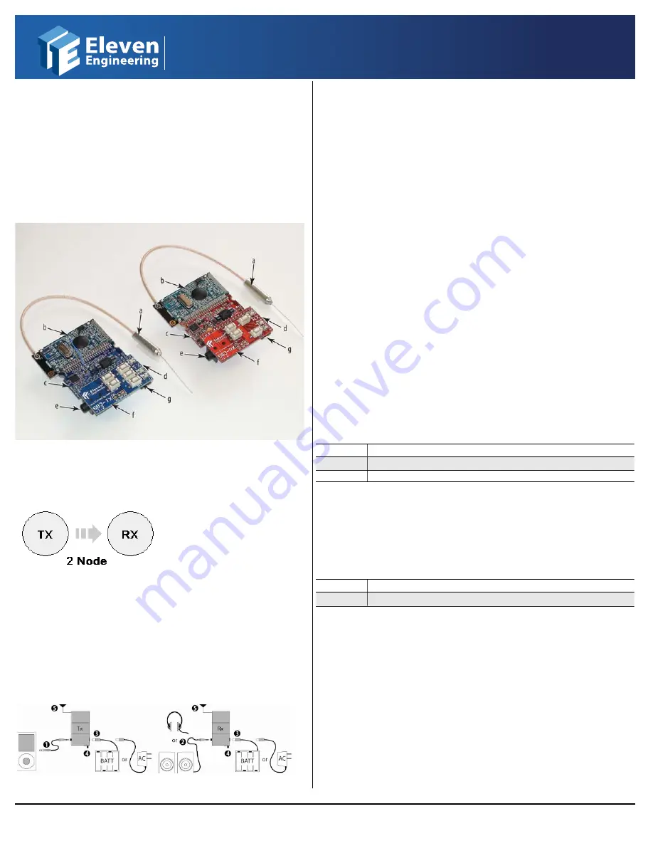
1. Evaluation Kit Diagram
a. Antenna
e. 3.5mm Stereo Audio Jack
b. SP-205 Module
f. SB3 Interface Board
c. PB3 Reference Board
g. Power Switch
d. Power Jack
Your kit is configured for 2-Nodes. This kit is a digital wireless audio 1.0
channel solution.
Rx node has audio on left channel only.
2. Evaluation Kit Setup
This SP-205 Evaluation kit is pre-assembled and pre-configured to work of
the box. Follow the simple steps outlined below to correctly setup and
begin using the evaluation kit.
1. Plug an audio cable into the audio jack on the Transmitter (Tx). Connect the
other end of the audio cable to an audio source, such as a portable media
player (Maximum input level is -3.5dBV).
2. Plug an audio cable into the audio jack on the Receiver (Rx). Connect the
other end of the cable to an audio amplifier, active speaker, or headphones.*
3. Connect the battery pack or AC adaptor (6V DC, 400mA) to the power jack on
the Tx and Rx.
4. Turn the power switches on both nodes to "on".
5. Make sure that antennas are in free space for best range, i.e. not resting
against a surface, PCB, or body.
Audio signals will begin transmission after step 4.
Please note that because this evaluation kit is electrostatic sensitive, it is
important to keep the Tx and Rx on electrostatic free surfaces.
*Headphones can be used for testing but since no headphone driver is included on the PB3 Rx board, the maximum
volume level may be lower than desired.
3. Evaluation Kit Features
The SP-205 system comes preloaded with firmware. This firmware implements
a number of useful user interface features such as LED blinking and push button
volume control. This section provides a brief summary of some commonly used
features of the firmware.
A. Bond LED:
The Bond LED displays the bond status between the Tx node
and the Rx nodes, as follows:
Solid On
Tx and Rx are bonded
Flashing
Node is searching for bond with its mate
Off
Board is powered off
Bond1 LED will start to flash when the Tx is powered on. When the Rx bonds to
the Tx it will cause the Bond1 LED on the Tx and the Bond LED on the Rx to turn
solid green.
B. Mute LED:
The Mute LED displays the audio status of the Rx node, as
follows:
Solid On
Audio is manually muted by User
Off
Audio can play normally
C. Volume / Mute Control:
Volume buttons on the Rx node will
increase/decrease the volume audio level by 1dB per button press for a total of
70 steps. Pressing and holding a volume button will ramp the volume quickly.
Maximum volume is 0dB and minimum volume is -70dB. NOTE: Volume
settings are stored and recalled on reboots. (Normal Default Setting: Max for left
channel)
The Volume and Mute buttons on the Tx node are currently not enabled.
D. Reset Button:
Pressing the Reset button will reset the entire module.
This button is sometimes useful when downloading new firmware.
SP
SP-205 Evaluation Kit Operating Instructions
DO4611
www.ElevenEngineering.com
Subject to change without notice.
DO4611|
2009.11.05
@2009 Eleven Engineering Inc. XInC
TM
, XInC2
TM
and their associated logos are trademarks
of Eleven Engineering Inc. Multiple Patents and Patents Pending. Other logos, designs, titles
or phrases may be trademarks of Eleven or other entities.


