background image

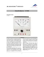
DIGITAL MULTIMETER KIT

MODEL M-1007K

Assembly and Instruction Manual

Elenco

®

Electronics, Inc.

Copyright © 2008 by Elenco

®

Electronics, Inc.  All rights reserved.

753096

No part of this book shall be reproduced by any means; electronic, photocopying, or otherwise without written permission from the publisher.

Summary of Contents for M-1007K

Page 1: ...d Instruction Manual Elenco Electronics Inc Copyright 2008 by Elenco Electronics Inc All rights reserved 753096 No part of this book shall be reproduced by any means electronic photocopying or otherwi...

Page 2: ...5 1 4W brown black green gold 171000 Resistors with 0 25 tolerance may be included instead of 0 5 These parts are not mounted on card r 1 R9 0 01 Shunt Wire 100165 r 1 VR1 220 221 Potentiometer 19131...

Page 3: ...ue printed in the following manner The maximum operating voltage may also be printed on the capacitor Second Digit First Digit Multiplier Tolerance For the No 0 1 2 3 4 5 8 9 Multiply By 1 10 100 1k 1...

Page 4: ...e solder for health reasons This kit contains lead free solder which contains 99 3 tin 0 7 copper and has a rosin flux core Lead free solder is different from lead solder It has a higher melting point...

Page 5: ...3 1 F 104 Mylar Capacitor small yellow C5 1 F 104 Mylar Capacitor small yellow R14 220k 5 1 4W Resistor red red yellow gold see Figure A R13 220k 5 1 4W Resistor red red yellow gold see Figure A Mount...

Page 6: ...nto the PC board from the top legend as shown in Figure E Solder the sockets to the PC board on the component side only The solder should extend completely around the socket see Figure E r Insert the...

Page 7: ...shown and push the edge of the LCD against the raised area on the case Press into place r Place the zebra onto the grooved surface of the LCD as shown in Figure H Carefully place the zebra clip around...

Page 8: ...r Place the PC board over the selector knob Be sure that the 8 pin socket slides into its hole Then fasten the PC board with three 6mm screws as shown in Figure K r Insert the 0 5A 250V fuse into the...

Page 9: ...is less wire between the 10A DC and COM sockets If the meter reads low resolder the shunt wire so that there is more wire between the sockets 1 ACV Range 750 HV 0 0 0 200 0 0 0 2 DCA 10A Ranges 200 0...

Page 10: ...and RA as in the following table Read the currents shown and compare to a known accurate meter If any of the above tests fail a Check the fuse b Check the value and soldering of resistors R8 R20 and...

Page 11: ...d insert a small transistor into the appropriate NPN or PNP holes in the transistor socket 2 Read the hFE of the transistor The hFE of transistors varies over a wide range but you will probably get a...

Page 12: ...t is clocked at about two readings per second The digitized measurements are presented to the display as four decoded digits seven segments plus polarity The decimal point position on the display is d...

Page 13: ...switch closes This applies a known reference voltage to the input to the A D converter The polarity of this voltage is automatically selected to be opposite that of the unknown input voltage thus cau...

Page 14: ...erters One inverter shown for clarity 7 6 4 OSC 1 OSC 2 OSC 3 DIGITAL SECTION ANALOG SECTION of 7106 CREF RINT CAZ CINT INT CREF REF HI REF LO CREF BUFFER V 35 42 44 43 41 36 37 1 AUTO ZERO A Z Z1 A Z...

Page 15: ...value required to give the correct RMS reading CURRENT MEASUREMENT Figure 6 shows a simplified diagram of the current measurement function Internal shunt resistors convert the current to between 0 19...

Page 16: ...simple series circuit is formed by the voltage source a reference resistor from the voltage divider selected by the selector switches and the test unknown resistor The ratio of the two resistors is e...

Page 17: ...not known set the switch to the highest range 4 Connect the leads across the points to be measured and read the display If the range switch is too high reduce it until a satisfactory reading is obtain...

Page 18: ...indicates that the battery should be replaced To replace battery and fuse 0 5A 250V remove the 2 screws in the bottom of the case Simply remove the old fuse battery and replace with a new fuse batter...

Page 19: ...18 SCHEMATIC DIAGRAM...

Page 20: ...Elenco Electronics Inc 150 Carpenter Avenue Wheeling IL 60090 847 541 3800 Website www elenco com e mail elenco elenco com 081212...

Reviews: