background image

EN 

Publication number 


Rev. 01 

09/2015 

PR - 1/17 


SERVICE MANUAL


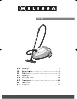
VACUUM CLEANER


Silent Performer Cyclonic 


Factory:  

HUV


¤

 E.H.P. Floor Care 


Number of 

publication 


 Edition: 2015 


EN 


Summary of Contents for EL4021A

Page 1: ...EN Publication number Rev 01 09 2015 PR 1 17 SERVICE MANUAL VACUUM CLEANER Silent Performer Cyclonic Factory HUV E H P Floor Care Number of publication Edition 2015 EN ...

Page 2: ...on number Rev 01 09 2015 PR 2 17 TABLE OF CONTENTS 1 General description 3 1 2 Exploded view 3 2 ACCESSIBILITY 5 3 Electronic Control 13 3 1 Motor power regulation 13 3 2 Electronic layout 15 4 Trouble shooting 16 ...

Page 3: ...EN Publication number Rev 01 09 2015 PR 3 17 1 General description Accessories may vary from model to model 1 1 Exploded view ...

Page 4: ...R 500A HYGIENE FILTER 350 LOWER PART WITH WHEELS 330 HOLDER FRONT WHEEL 119B FRONTWHEEL 335B REARWHEEL 119A HOSE CONNECTION OUTER 550B HOSE CONNECTION INNER 550A LID FRONT 309 SIDE PANEL LEFT 326A SIDE PANEL RIGHT 326B DUST CONTAINER 302 LID TIP RIGHT 325B CORD WINDER PEDAL 329 LID TOP LEFT 325A LID FINE DUST 310 DUST COMPARTMENT 301 LID HOSE CONNECTION 551 HOSE 110 HANDLE 127A TELESCOPIC TUBE 127...

Page 5: ... the vacuum cleaner Tags have been added to help finding quickly the needed item to be removed quickly ATTENTION Boards and electronic devices could be damaged by electrostatic discharges Don t touch any components without any ESD protection At first step remove the dust compartment from the appliance Then remove the fine dust lid Click out the CW pedal snapping ribs at both side ...

Page 6: ...N Publication number Rev 01 09 2015 PR 6 17 Now you can take out the CW pedal easily Remove two screw from the CW pedal nest To remove the top cover need to click out the snappers at the following places ...

Page 7: ...EN Publication number Rev 01 09 2015 PR 7 17 Now you can remove the lid easily To remove the left side top cover click out the snappers at the following places Now its easy to remove the lid by hand ...

Page 8: ...EN Publication number Rev 01 09 2015 PR 8 17 Remove the 4 screw from the cyclone unit Than take out the cyclone unit and the air channel Remove the screw from the rear side ...

Page 9: ...N Publication number Rev 01 09 2015 PR 9 17 Pull the regilation button to the minimum position Click out the side cover fixing ribs trough the service holes on the bottom part Remove the right side cover ...

Page 10: ...R 10 17 Click out the left side cover fixing ribs trough the service holes on the bottom part Then remove the left side cover Remove the screws from the front lid Click out the snappers at both side Rotate the hose connection ring clockwise ...

Page 11: ... 01 09 2015 PR 11 17 Now remove the front lid and hose connection ring from the appliance Take out the motor house from the bottom plate Remove the Hepa filter frame from the back side Remove the screws from the motor house lid ...

Page 12: ...EN Publication number Rev 01 09 2015 PR 12 17 Remove the motor house lid Pull out the suspension ring from the motor house Now you can reach the motor ...

Page 13: ... 2 RF transmitter Introduction The RF transmitter is used as remote control for a vacuum cleaner powered by a 3V changeable lithium cell The transmitter uses the 2 4 GHz carry over from Ceres Castor band for transmitting data inside EU With the transmitter it is possible to turn the appliance on and off and regulate the motor power Estimated lifetime for the battery in normal use is approximately ...

Page 14: ...ou have 20s after connection to main If the cleaner received the right reset signal it will fluctuate 3 Unplug the cord from the main 4 Wait min 5sec 5 Plug in the cord to the main again The cleaner should fluctuate 6 Send teaching signal 1 3 button combination at the same time to do this you have 20s after connection to main 7 If the teaching was successful the cleaner will turn on 1 5s and after...

Page 15: ...r Rev 01 09 2015 PR 15 17 3 2 Electronic layout Angerona L1 model Angerona L2 model ATTENTION Boards and electronic devices could be damaged by electrostatic discharges Don t touch any components without any ESD protection ...

Page 16: ...between Power module and control unit for failure or bad connection Change the control unit Change the Power module Cleaner doesn t start Check motor voltage if no voltage check the electronics as below else check motor TCO and motor Check communication wire between Power module and control unit for failure or bad connection Change the control unit Change the Power module Not ponssible to change p...

Page 17: ...EN Publication number Rev 01 09 2015 PR 17 17 ...

Reviews: