


SOI 05.09 FV
1/36
599 71 58-20
SERVICE MANUAL
COOKING
ã ELECTROLUX ITALIA S.p.A.
Corso Lino Zanussi, 30
Publication
number
I - 33080 PORCIA /PN (ITALY)
599 71 58-20
Fax +39 0434 394096
SOI
Edition: 05.2009 - Rev. 00
EN/SERVICE/FV
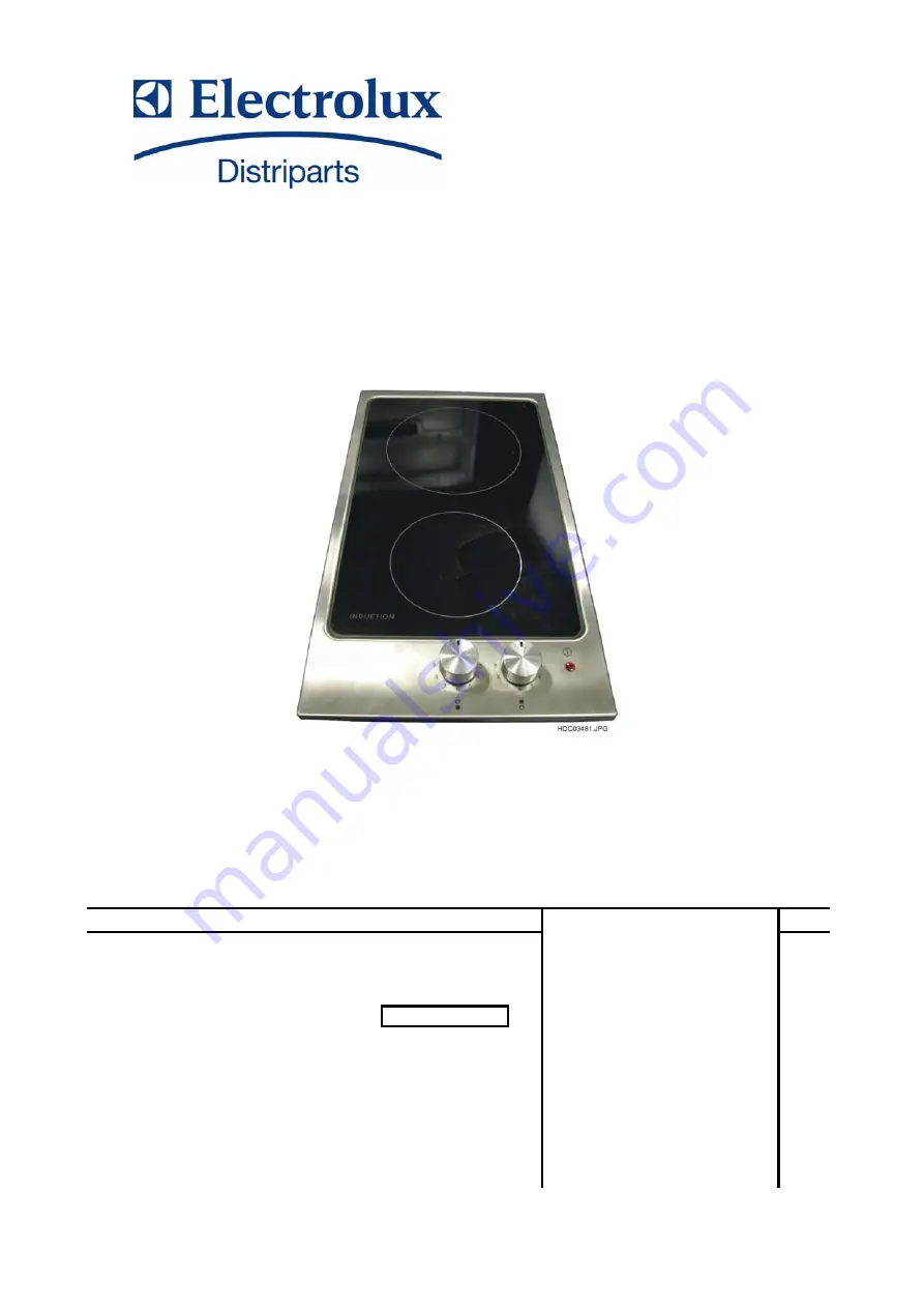
Built-in hobs
"DOMINO" MAGNETIC
INDUCTION HOBS WITH
"TIGER" CIRCUIT BOARD
AND ROTARY
CONTROLS


