Electrolux 65557 G-M, Instruction Booklet
The Electrolux 65557 G-M Instruction Booklet is an essential manual for operating your product seamlessly. This comprehensive guide is available for free download on manualshive.com, ensuring easy access to important information and instructions. Get the most out of your Electrolux 65557 G-M with this reliable and user-friendly manual.
Share
Download


Reviews:
No comments
Related manuals for 65557 G-M

T21S31N1
Brand: BALAY Pages: 12

88031K-MN
Brand: AEG Electrolux Pages: 24

SI5643B
Brand: Smeg Pages: 22

MH-7320 R
Brand: Malloca Pages: 56

UBINDECO60F
Brand: Apelson Pages: 24

ZPI6016UE
Brand: Zelmer Pages: 32

FTGHG 751 D/A/LPG
Brand: Ariston Pages: 40

AR49
Brand: ROSENLEW Pages: 2

SI2M7953DW
Brand: Smeg Pages: 20

RH60EH401B
Brand: Russell Hobbs Pages: 24
C61R1ABMAL
Brand: Samsung Pages: 34
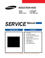
C61R1AAMST
Brand: Samsung Pages: 41
C61R2AEE
Brand: Samsung Pages: 70
C61R1AAMST
Brand: Samsung Pages: 352

GTH63XS
Brand: Glem Pages: 52

OCD 608 YI
Brand: arcelik Pages: 16

Toptronic GK45TEASC
Brand: V-ZUG Pages: 8

HBE 2I2G FV
Brand: Eurolux Pages: 32


