manualshive.com logo in svg
background image

Installation manual

Tumble dryer

PD9C

Type N1190..

Original instructions

438 9055-00/EN

2022.10.06

Содержание PD9C

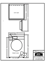
Страница 1: ...Installation manual Tumble dryer PD9C Type N1190 Original instructions 438 9055 00 EN 2022 10 06 ...

Страница 2: ......

Страница 3: ...m 15 7 1 Air principle 15 7 2 Fresh air 15 7 3 Exhaust duct 15 7 4 Shared exhaust duct 16 7 5 Exhaust dimensioning 16 8 Electrical connection 17 8 1 Electrical installation 17 8 2 Single phase connection 18 8 3 Three phase connection 18 8 4 Electrical connections 19 8 5 Option 19 9 At first power up 20 9 1 Select language 20 9 2 Set time and date 20 10 Function check 21 11 Disposal information 22 ...

Страница 4: ......

Страница 5: ...ust not be installed behind a lockable door a sliding door or a door with a hinge on the opposite side to that of the machine in such a way that a full opening of the machine is restricted If the machine has a lint trap this has to be cleaned frequently The lint must not be accumulated around the machine DO NOT MODIFY THIS APPLIANCE When performing service or replacing parts the power must be disc...

Страница 6: ...ing or area Contact the person responsible for the machine Additional requirements for the following countries AT BE BG HR CY CZ DK EE FI FR DE GR HU IS IE IT LV LT LU MT NL NO PL PT RO SK SI ES SE CH TR UK The appliance can be used in public areas This appliance can be used by children aged from 8 years and above and persons with reduced physical sensory or mental capabilities or lack of experien...

Страница 7: ...Installation manual 7 1 3 Symbols Caution Caution hot surface Caution high voltage Read the instructions before using the machine ...

Страница 8: ...es and or other that does not comply with the technical requirements for each appliance plumbing parts components or consumable cleaning products that are not approved by the manufacturer customer s negligence misuse abuse and or non compliance with the use and care instructions detailed within the appropriate equipment documentation improper or poor installation repair maintenance including tampe...

Страница 9: ...manual 9 3 Technical data 3 1 Drawing C A 1 2 D B a B b 3 E F G H 4 1 Operating panel 2 Door opening 400 mm 3 Electrical connection 4 Exhaust connection A B a B b C D E mm 721 759 684 1114 404 45 F G H mm 180 88 113 ...

Страница 10: ...heating 8 kW m3 h 290 Pressure drop Electric heating 6 kW Max Pa 120 Pressure drop Electric heating 8 kW Max Pa 70 A weighted emission sound pressure level at working stations dB A 70 3 3 Connections Air outlet mm 125 Gas connection 1 2 ISO 7 1 R1 2 4 Setup 4 1 Unpacking Cut and remove the two plastic straps between the machine and pallet There is one strap on each side of the machine fig 7676 Rem...

Страница 11: ... personnel The figure shows minimum distance to a wall and or other machines 400 mm 15 3 4 inch 10 mm 3 8 inch 10 mm 3 8 inch fig 6320A 4 3 Mechanical installation Level the machine with the feet of the machine The maximum height adjustment of the feet is 50 mm If the machine is mounted on a base it needs to be fastened to the base fig 6321 ...

Страница 12: ... with the marine machine model to the foundation using four x M10 set screws If the four fittings are not supplied order kit No 487193544 Fasten the machine to the fittings Note Marine installation is not applicable for gas heated machines 675 mm 26 9 16 inch M10 M10 M10 M10 600 mm 23 5 8 inch 400 mm 15 3 4 inch M10 20Nm 512 mm 20 5 32 inch 585 mm 23 1 32 inch fig 6322 ...

Страница 13: ... order to secure the panel on the back Mount the hinge A at the bottom of the opposite side Demount the door by carefully lifting it of the front Demount hinge B A A B fig 7993 Demount the top panel Cut the cable tie and remove cable C to the opposite side Demount the plastic cover with door switch D and mount on the opposite side C D fig 7657 ...

Страница 14: ...pposite side using the existing scews Mount the door by lifting it back on the fitting on the opposite side Mount the hinge B at the top B fig 7658 Demount the magnetic door lock E and magnet for switch F and mount on the opposite side F E fig 7659 Connect the power to the machine Test run the machine ...

Страница 15: ...be five times the size of the exhaust pipe area The area of the inlet opening is the area through which the air can flow without resistance from the grating slatted cover 5 x A A fig 6312 Note Gratings slatted covers often block half of the total fresh air vent area Remember to take this into account 7 3 Exhaust duct Only rigid or flexible metal duct should be used for exhausting Plastic ducting i...

Страница 16: ...Exhaust duct mm 125 200 250 250 315 315 400 400 400 400 Recommended area of fresh air intake m2 0 06 0 16 0 25 0 25 0 39 0 39 0 63 0 63 0 63 0 63 Minimum area of fresh air intake m2 0 03 0 06 0 09 0 12 0 15 0 18 0 21 0 24 0 27 0 3 The exhaust duct diameter must not be reduced 7 5 Exhaust dimensioning It is important that the machine has correct air volume compared to each machines power If the air...

Страница 17: ...sonal safety which is why items of external equipment such as earth leakage circuit breakers are not necessary but is recommended If you still want to connect your machine across an earth leakage circuit breaker please remember the following contact a skilled authorised installation company to ensure that the appropriate type of breaker is chosen and that the dimensioning is correct for maximum re...

Страница 18: ... That the machine operates by connecting the power to the machine and start a program with heat 8 3 Three phase connection Demount the cover panel from the supply unit Connect the earth and other wires as shown 3AC L3 L2 L1 N 3AC L1 L2 L3 3NAC L3 L2 L1 N 3NAC N L1 L2 L3 When the installation is completed remount the cover panel and check That the drum is empty That the machine operates by connecti...

Страница 19: ...0 8 0 6 3 8 3 10 16 440 480V 3 60 6 0 8 0 6 3 8 3 10 16 230V 1N 50 6 0 8 0 6 3 8 3 35 50 400V 3N 50 6 0 8 0 6 3 8 3 10 16 8 5 Option External connection A special connection terminal is located on the motor bracket This connection can be used as external control of a fan The terminal for external control is equipped with 110V max 100 mA and is intended solely for the operation of a contactor Max c...

Страница 20: ...Select language from the list on the display This will be the language that all display messages program names etc will be presented in 9 2 Set time and date Select YES and press the control knob to get to the menu TIME DATE Activate the SET TIME menu and set the correct time Save the settings Activate the SET DATE menu and set the correct date Start by setting the year Set the year Exit to contin...

Страница 21: ...d Check the direction of rotation only on machines with 3 phase power supply marine installation Demount the top panel and start a program Check that the drum rotation is clockwise fig 6311 If the direction is wrong swap two of the three phases to the left on the connection terminal fig 7119 Check the heat Let the machine work for five minutes on a program with heat Check that the heating is worki...

Страница 22: ...ecycled and that the refrigerator and heat pump components are special waste assimilable with urban waste The symbol on the product indicates that this product should not be treated as domestic waste but must be correctly disposed of in order to prevent any negative consequences for the environment and human health For further information on the recy cling of this product contact the local dealer ...

Страница 23: ......

Страница 24: ...Electrolux Professional AB 341 80 Ljungby Sweden www electroluxprofessional com ...

Отзывы: