background image


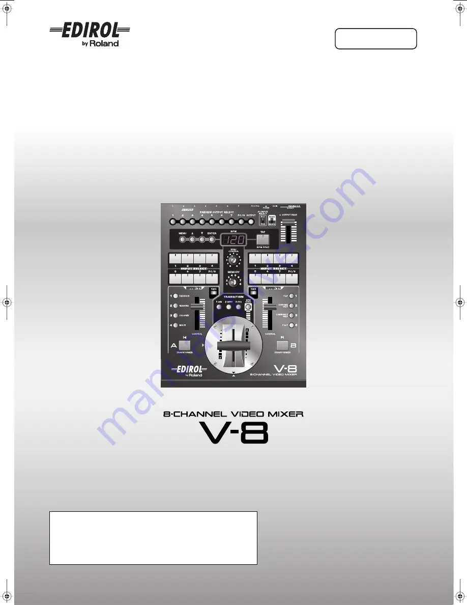
Owner’s Manual

Before using this unit, carefully read the sections entitled: “USING THE UNIT 
SAFELY” and “IMPORTANT NOTES” (p. 6–7; p. 8). These sections provide 
important information concerning the proper operation of the unit. Additionally, 
in order to feel assured that you have gained a good grasp of every feature 
provided by your new unit, Owner’s Manual should be read in its entirety. The 
manual should be saved and kept on hand as a convenient reference.


Copyright © 2008  ROLAND CORPORATION


All rights reserved. No part of this publication may be reproduced in any form without 
the written permission of ROLAND CORPORATION.

V-8_e.book 1 ページ 2008年5月15日 木曜日 午後1時11分

Summary of Contents for V-8

Page 1: ...f the unit Additionally in order to feel assured that you have gained a good grasp of every feature provided by your new unit Owner s Manual should be read in its entirety The manual should be saved and kept on hand as a convenient reference Copyright 2008 ROLAND CORPORATION All rights reserved No part of this publication may be reproduced in any form without the written permission of ROLAND CORPO...

Page 2: ...manual this document IMPORTANT THE WIRES IN THIS MAINS LEAD ARE COLOURED IN ACCORDANCE WITH THE FOLLOWING CODE BLUE BROWN As the colours of the wires in the mains lead of this apparatus may not correspond with the coloured markings identifying the terminals in your plug proceed as follows The wire which is coloured BLUE must be connected to the terminal which is marked with the letter N or coloure...

Page 3: ... are being input to channels 5 7 or if both an S video signal and a computer output signal are being input to channel 8 the input from the S video connector will take priority and will be sent from monitor out The input signal from the computer will also be sent from monitor out as a video signal High quality digital effects Digitally processed effects are built in You can apply a variety of high ...

Page 4: ...tings to the Factory Set State Factory Reset 33 Returning All Settings to the Factory Set State 33 Returning the Settings of a Specific Sub Menu to the Factory Set State 34 Switching Between Two Images 35 Changing the Transition Assigned to Each TRANSITION Button 36 Combining Multiple Transition Effects User Transition 38 Using the TRANSFORMER Buttons to Switch Images 40 Changing the Assignment of...

Page 5: ... to an External MIDI Device 69 Restoring Data Saved on an External MIDI Device Back into the V 8 70 Sending the V 8 s Settings to Another V 8 71 Controlling via V LINK 72 What is V LINK 72 Controlling the RSS M 400 from the V 8 V LINK Master 72 Controlling the V 8 from an External V LINK Compatible Device V LINK Slave 74 Using the V 8 in Conjunction with the PR Series PR Control mode 75 Installing...

Page 6: ... penetrate the unit 012b Immediately turn the power off remove the AC adaptor from the outlet and request servicing by your retailer the nearest EDIROL Roland Service Center or an authorized EDIROL Roland distributor as listed on the Information page when The AC adaptor the power supply cord or the plug has been damaged or If smoke or unusual odor occurs Objects have fallen into or liquid has been...

Page 7: ...this unit 103b At regular intervals you should unplug the AC adaptor and clean it by using a dry cloth to wipe all dust and other accumulations away from its prongs Also disconnect the power plug from the power outlet whenever the unit is to remain unused for an extended period of time Any accumulation of dust between the power plug and the power outlet can result in poor insulation and lead to fi...

Page 8: ... data However in certain cases such as when circuitry related to memory itself is out of order we regret that it may not be possible to restore the data and Roland assumes no liability concerning such loss of data This unit allows you to switch images or turn video effects on off at high speed For some people viewing such images can cause headache nausea or other discomfort Do not use this unit to...

Page 9: ...lock Diagram p 108 fig signal flow e eps The preview output will also show the settings menu of the V 8 overlaid with the image p 23 INPUTs 5 7 provide composite connectors and S video connectors If an image is being input to both connectors of the same channel the input from the S video connector will take priority INPUT 8 provides both an S video connector and a PC connector If an image is being...

Page 10: ...Button You can specify the BPM by pressing the TAP button at the desired interval Switching Images at the Tempo Specified by the TAP Button p 61 BPM CONTROL Knob Use this to edit the BPM value If you ve used the TRANSITION buttons to select 003 Fam or 005 Nam as the transition effect this will adjust the way in which the transition occurs About the FAM and NAM Transition Effects p 37 MEMORY Knob T...

Page 11: ...ientation p 76 TRANSITION Buttons Here you can select the way in which you will transition between the bus A and bus B images The button you ve selected will light The settings listed below are for memory number 1 of the MEMORY knob By selecting memory numbers 2 8 you can assign different transition effects to each TRANSITION button Switching Between Two Images p 35 BPM SYNC Button This lets you a...

Page 12: ... p 107 The settings listed below are the settings for memory number 1 of the MEMORY knob By selecting memory numbers 2 8 you can assign other effects to the EFFECTS buttons Assigning Different Effects to the EFFECTS Buttons p 53 Bus B CONTROL Fader You can use this fader to control the settings of an effect assigned to the blinking EFFECTS button Effects that can be controlled by the CONTROL fader...

Page 13: ...ector channel 8 This is a BNC connector that outputs a composite video signal of the image that is being input to the channel 8 S video connector or to the PC1 PC2 input connector Here you can connect a television monitor that has a composite video input connector and use it to view the input image The input from the S video connector will take priority for channel 8 If the connection cable you re...

Page 14: ...or 1 S video input connector Monitor the 1 7 inputs Preview monitor Composite input connector 1 Composite output connector 1 VGA output connector S video output connector S video cable S video cable Ground terminal Composite cable Composite cable Composite cable RCA BNC adaptor plugs Composite cable Composite cable RCA BNC adaptor plugs RCA BNC adaptor plugs RCA BNC adaptor plugs RCA BNC adaptor p...

Page 15: ...an infinitesimal electrical charge which is absolutely harmless However if you are concerned about this connect the ground terminal with an external ground When the unit is grounded a slight hum may occur depending on the particulars of your installation If you are unsure of the connection method contact the nearest EDIROL Roland Service Center or an authorized EDIROL Roland distributor as listed ...

Page 16: ... live images live image DVD computer image You can use the Picture In Picture effect to display two images simultaneously p 43 Since a scan converter is built in still images and the like from a computer can be input directly Events Examples of Using the V 8 Composite Composite Composite S video Projector Large display Output video device Multi monitor Computer Preview Preview monitor VGA Composit...

Page 17: ...nal transition pattern User Transition p 38 You can use numerous effects such as Feedback After image and Silhouette Since a scan converter is built in video from a computer VJ software can be input directly You can also use the V 8 s Zoom function to input just a portion of the image You can use the V 8 s CONTROL faders to dynamically apply an effect or fade to the input signal You can set the V ...

Page 18: ...u can use Luminance keying to superimpose text or graphics on an image p 46 Since a scan converter is built in you can directly input presentation material from your computer Since there are two PC inputs you can connect and use two computers Presentations Composite Composite S video VGA VGA Composite S video Output video device DV camera DVD player Computer Preview monitor Preview Projector Large...

Page 19: ...ttings can be dramatically simplified You can control the M 400 in synchronization with the switching of images Advantages of using the V 8 Using V LINK lets you synchronize the V 8 s video fader operations with the M 400 s audio input levels Background Video for a Musical Performance Using V LINK Using the V 8 with the RSS M 400 Using V LINK Composite Composite S video VGA MIDI V LINK Composite S...

Page 20: ...wer on e eps If you ve used a menu operation p 24 to modify any parameters close the menu before you turn off the power If you turn off the power before closing the menu the changes you made will be discarded 1 Press the POWER switch located on the V 8 s rear panel to turn it off Turning the Power On Turning the Power Off Turning the Power On Off On Off V 8 Rear panel ...

Page 21: ... PC 8 buttons for bus A Move the video fader to the bus B position Switch between inputs by successively pressing the INPUT SELECT 1 PC 8 buttons for bus B When you use the PC INPUT SELECT switch to switch the PC input it will take some time for the input to stabilize We recommend that you use a monitor to verify the image In addition selecting the PC input may cause the image display position to ...

Page 22: ...ew Image 1 PC 8 buttons Sends the video being input via the INPUT 1 8 PC1 PC2connectors to the preview output For channels 5 8 the input from the S video connectors will take priority Use the PC INPUT SELECT switch to change between the PC1 PC2 connector inputs OUTPUT button Sends the final image to the preview output Preview output when there is no signal Value Details On The No Signal indication...

Page 23: ...have your TV monitor connected to the PREVIEW OUT connector and ready for use fig connect monitor e eps Menus are arranged as shown in the figure below The value are set in the lowest level in each respective parameter fig menu images e eps Preparations for Viewing the Menu About menu levels Menu Operations TV monitor V 8 Rear panel 1 Mix Trans1 001 Mix01 002 Fam01 003 Fam 2 Wipe Trans2 001 Mix01 ...

Page 24: ...button to access the menu fig menu1 eps 2 Use the buttons to select a menu item fig menu2 eps The buttons move the cursor up down The menu item at the cursor will blink indicated that it is selected 3 Press the ENTER button to confirm your choice of menu item fig menu3 eps The selected menu item will be confirmed and you ll proceed to the next menu a lower level To return to the previous menu high...

Page 25: ...our changes will be lost By turning the Utility menu item Memory Protect to the On setting you can prevent changes to the settings If memory protect is on the memory screen will indicate Protect On fig menu protect eps You can adjust the location in which menus and settings p 26 are shown in the preview monitor To make this adjustment use the Utility menu items OSD Horizontal Locate horizontal pos...

Page 26: ... you re using the BPM Sync function p 60 fig preview fader position e eps This indication is shown when the position of the video fader differs from the actual output Bus fade indication fig preview fade e eps When the CONTROL faders can be used to fade the bus image p 31 a symbol is shown beside the FADE indication About the Current Settings Display Preview output channel PC INPUT SELECT switch s...

Page 27: ...o select Utility Press the ENTER button to confirm your selection 2 Use the buttons to select Preview Display Mode and press the ENTER button fig menu utl prvdisp eps_18 3 Use the buttons to select the contents of the information that will be shown in the preview monitor 4 Press the MENU button several times to close the menu Changing the Contents of the Settings Display Value No Display Mode1 Mod...

Page 28: ...MORY Knob Operating panel Factory preset memory number 1 Stored setting See page TRANSITION buttons 1 MIX 001 Mix01 Transition effect assigned to each button p 36 2 WIPE 008 Wipe03 3 EFX 192 SWipe88 BPM SYNC button Mode TransitionA B Speed BPMx1 Transition mode and displayed BPM when using BPM sync p 60 p 62 Bus A EFFECTS buttons 1 FEEDBACK 022 FEEDBACK Effect setting assigned to each button p 53 ...

Page 29: ...U button to access the menu Use the buttons to select Memory Edit Press the ENTER button to confirm your selection 3 Use the buttons to select the desired copy destination memory number and press the ENTER button fig menu memory c eps_18 fig memory copy e eps To copy the contents of memory choose an item that shows Copy at the left side In the screen example shown here the settings of memory numbe...

Page 30: ...ection 3 Use the buttons to select the desired exchange destination memory number and press the ENTER button fig menu memory e eps_18 fig memory exchange e eps To exchange the contents of memory choose an item that shows Exchange at the left side In the screen example shown here the settings of memory number 2 will be exchanged with the settings of memory number 8 You can change the exchange sourc...

Page 31: ...the image raise the CONTROL fader The fade color is fixed at black To fade out the bus B image operate the bus B FADE button and CONTROL fader in the same way Fading Out the Bus A Bus B Image Fading Out the Output Image In addition to controlling bus fading the CONTROL fader is also used to control the effect settings p 42 While the EFFECTS button is blinking operating the CONTROL fader will affec...

Page 32: ...ect the memory number 2 8 whose setting you want to edit Memory number 1 contains the factory preset settings p 28 These settings cannot be modified 2 Press the MENU button to access the menu and choose Output Fade fig menu output fade eps_18 Press the MENU button to access the menu Use the buttons to select Output Fade Press the ENTER button to confirm your selection 3 Use the buttons to specify ...

Page 33: ...u execute a Factory Reset 1 Press the MENU button to access the menu and choose Factory Reset fig menu factory eps_18 Press the MENU button to access the menu Use the buttons to select Factory Reset Press the ENTER button to confirm your selection 2 Use the buttons to select Yes ENTER Sw and press the ENTER button If you decide to cancel press the MENU button or select No and press the ENTER butto...

Page 34: ...nu Use the buttons to select Utility Press the ENTER button to confirm your selection 2 Use the buttons to choose Utility Reset and press the ENTER button fig menu utl reset eps_18 3 Use the buttons to choose Yes ENTER Sw and press the ENTER button If you decide to cancel press the MENU button or choose No and press the ENTER button A factory reset will be executed for the Utility sub menu 4 Press...

Page 35: ...hanging the Transition Assigned to Each TRANSITION Button p 36 Depending on the type of transition and effect p 42 there are some combinations that cannot be used simultaneously For details refer to Effects that Cannot Be Used Simultaneously p 107 4 Operate the video fader to switch between the images of bus A and bus B To output the bus A image move the video fader toward bus A To output the bus ...

Page 36: ...t image For details on the transition effects refer to Transition Effect List p 99 4 Press the MENU button several times to close the menu Button Menu item 1 MIX button 1 Mix Trans1 2 WIPE button 2 Wipe Trans2 3 EFX button 3 Efx Trans3 Changing the Transition Assigned to Each TRANSITION Button If you ve chosen 003 Fam or 005 Nam as the effect selected by a TRANSITION button you ll be able to use t...

Page 37: ... 0 100 About the FAM and NAM Transition Effects Changing the cross point of the FAM NAM 003 Fam 005 Nam Dissolve transition 001 Mix01 FAM transition 002 Fam01 003 Fam NAM transition 004 Nam01 005 Nam Dissolve transition The transition between images takes place by simply raising or lowering the video level The luminance of the composite image will be less in the region of the cross point FAM trans...

Page 38: ... positions and press the ENTER button 3 Use the buttons to specify the transition effect for each position 4 Press the MENU button several times to close the menu Combining Multiple Transition Effects User Transition Transition effects Menu item 260 User01 User Transition1 261 User02 User Transition2 262 User03 User Transition3 263 User04 User Transition4 Menu item Details Position1 Specifies the ...

Page 39: ...that you want to edit Press the ENTER button to confirm your selection 2 Use the buttons to select Switching and press ENTER 3 Use the buttons to turn the switching function on off 4 Press the MENU button several times to close the menu 5 Turn the BPM CONTROL knob or press the TAP button to specify the BPM User transition switching function Transition effects Menu item 260 User01 User Transition1 ...

Page 40: ...to switch between the bus A or bus B images If the video fader is in the bus B position The bus A image will be output only while you hold down the bus A TRANSFORMER button If the video fader is in the bus A position The bus B image will be output only while you hold down the bus B TRANSFORMER button With the factory preset settings the TRANSFORMER buttons are assigned to operate as follows You ca...

Page 41: ...on will not do anything 02 Trans The image of the bus whose button you press will be output as long as you hold down the TRANSFORMER button 03 A 9 12 A 0 1 03 9 B 12 0 B 1 The bus A and bus B images will alternate each time you press the TRANSFORMER button 13 A 9 22 A 0 1 13 9 B 22 0 B 1 The output will switch to the bus A image when you press the TRANSFORMER button The output will switch to the b...

Page 42: ...that Can Be Controlled by the CONTROL Fader p 106 The effect settings are stored in the V 8 when you turn off the effect When you once again turn the effect on the stored settings will be applied regardless of the position of the CONTROL fader In addition to controlling the effect settings the CONTROL fader is also used to control bus fading operations p 31 While the FADE button is blinking operat...

Page 43: ...d output 6 Operate the bus B CONTROL fader to change the position of the subscreen The blinking of the 4 P in P button indicates that you can use the CONTROL fader to change the position of the subscreen eight types The position of the subscreen will reflect the 142 PinP1 149 PinP8 setting p 44 7 Press the 4 P in P button once again to turn off the P in P effect The 4 P in P button will go out Usi...

Page 44: ...utton several times to close the menu Detailed settings for the P in P effect PinP effect Menu item PinP effect Menu item 142 PinP1 PinP Setup1 146 PinP5 PinP Setup5 143 PinP2 PinP Setup2 147 PinP6 PinP Setup6 144 PinP3 PinP Setup3 148 PinP7 PinP Setup7 145 PinP4 PinP Setup4 149 PinP8 PinP Setup8 Menu item Details PinP Hposi Adjusts the horizontal position of the subscreen PinP Vposi Adjusts the v...

Page 45: ...key effect will be applied to the bus B image and it will be combined with the bus A image and output 6 Operate the bus B CONTROL fader to adjust the key level The 2 CHROMA KEY button blinks to indicate that you can use the CONTROL fader to control the Chroma key level 7 Press the 2 CHROMA KEY button once again to turn off the Chroma key effect The 2 CHROMA KEY button will go out Using Chroma Key ...

Page 46: ...the bus A image and output 6 Operate the bus B CONTROL fader to adjust the white luminance level The 3 LUMINANCE KEY button blinks to indicate that you can use the CONTROL fader to control the white luminance level 7 Press the 3 LUMINANCE KEY button once again to turn off the Luminance key effect The 3 LUMINANCE KEY button will go out Using Luminance Key to Combine Images For each bus you can use ...

Page 47: ... edge level etc 4 Press the MENU button several times to close the menu Detailed settings for key compositing effects Menu item Details White LumiKey Level Adjusts the level for luminance keying extract white White LumiKey Edge Adjusts the soft edge level for luminance keying extract white Black LumiKey Level Adjusts the level for luminance keying extract black Black LumiKey Edge Adjusts the soft ...

Page 48: ...s A output image 5 Operate the bus A CONTROL fader to modify the brightness inversion or color inversion The blinking of the 2 NEGATIVE button indicates that you can use the CONTROL fader to modify the brightness inversion or color inversion 6 Press the 2 NEGATIVE button once again to turn off the Negative effect The 2 NEGATIVE button will go out Inverting the Image to Form a Negative Changing the...

Page 49: ...ze effect The 3 COLORIZE button will blink and the Colorize effect will be applied to the bus A output image 5 Operate the bus A CONTROL fader to change the colorization pattern The blinking of the 3 COLORIZE button indicates that you can use the CONTROL fader to change colorization patterns eight types 6 Press the 3 COLORIZE button once again to turn off the Colorize effect The 3 COLORIZE button ...

Page 50: ...the image onto itself the effect will gradually become stronger 5 Operate the bus A CONTROL fader to change the strength of the Feedback effect The blinking of the 1 FEEDBACK button indicates that you can use the CONTROL fader to change the strength four levels of the Feedback effect 6 Press the 1 FEEDBACK button once again to turn off the Feedback effect The 1 FEEDBACK button will go out Repeated...

Page 51: ...he 4 MULTI button will blink and the multi screen effect will be applied to the bus A output image 5 Operate the bus A CONTROL fader to change the dividing pattern for the screen The blinking of the 4 MULTI button indicates that you can use the CONTROL fader to switch between dividing patterns seven types 6 Press the 4 MULTI button once again to turn off the Multi screen effect The 4 MULTI button ...

Page 52: ...flipped 5 Operate the bus B CONTROL fader to change the direction of the flip The blinking of the 1 FLIP button indicates that you can use the CONTROL fader to switch between different directions three choices for the Flip effect 6 Press the 1 FLIP button once again to turn off the Flip effect The 1 FLIP button will go out Inverting the Image Flip For each bus you can use up to four effects simult...

Page 53: ... want to change Press the MENU button to access the menu and choose A Efx1 A Efx4 or B Efx1 B Efx4 Select the menu item for the button whose assignment you want to change If you ve selected bus A If you ve selected bus B Press the ENTER button to confirm your selection 4 Use the buttons to specify to the desired effect type If you press the corresponding EFFECTS button so it s lit or blinking and ...

Page 54: ...ns to select the item you want to edit and press the ENTER button 4 Use the buttons to edit the value 5 Press the MENU button several times to close the menu Adjusting the PC Input Image Menu item Details Hposition Adjusts the display position in the horizontal direction Vposition Adjusts the display position in the vertical direction Hsize Adjusts the size in the horizontal direction Vsize Adjust...

Page 55: ...rief interval the input resolution will be automatically detected and the output image will be resized In the PC Input Setup menu turn the Auto Detect setting Off Automatic detection of the input resolution will be turned off Display the original image figure 1 About the input resolution Resolutions 640 x 480 800 x 600 832 x 624 1 1024 x 768 Maximum refresh rate 120 Hz 120 Hz 75 Hz 80 Hz Resolutio...

Page 56: ...output from your video device is lower than the normal level In such cases try adjusting the Utility menu item Video Sync Threshold This may allow synchronization to be achieved so that the image will display properly Adjusting the Input Image for Bus A and B Menu item Content VideoA Bright Adjust Adjusts the brightness of the image being input to bus A VideoA Color Adjust Adjusts the color of the...

Page 57: ...nfirm your selection 2 Referring to the table below use the buttons to select the menu item that you want to adjust and press the ENTER button 3 Use the buttons to edit the value 4 Press the MENU button several times to close the menu Menu item Explanation Video Display Range H Adjusts the horizontal size of the final output image Video Display Range V Adjusts the vertical size of the final output...

Page 58: ...e MENU button to access the menu Use the buttons to select Utility Press the ENTER button to confirm your selection 2 Use the buttons to choose Color Bar Out and press the ENTER button 3 Use the buttons to choose On Color bars will be output 4 Press the MENU button several times to close the menu Value Details On Color bars will be output Off Color bars will not be output Outputting Color Bars ...

Page 59: ... confirm your selection 2 Use the buttons to select NTSC PAL and press the ENTER button 3 Use the buttons to choose NTSC or PAL The input output format will change 4 Press the MENU button several times to close the menu You can also switch between NTSC and PAL when the V 8 starts up 1 While holding down the PREVIEW OUT SELECT 1 button and OUTPUT button turn on the power The V 8 will start up with ...

Page 60: ...he FAM NAM cross point level p 37 will blink in the BPM display Turning the BPM CONTROL knob will adjust the cross point level If you want to change the BPM use the TAP button p 61 4 Press the BPM SYNC button The BPM SYNC button will light and the images will switch automatically at the specified BPM If you want to change the timing at which the images switch turn the BPM CONTROL knob to adjust th...

Page 61: ...dly press the TAP button in time with the beat of the background music you re using The BPM indication will change continuously according to the timing at which you press the TAP button The image will switch according to the displayed BPM If you ve selected 003 Fam or 005 Nam as the transition effect applied by a TRANSITION button the FAM NAM cross point level p 37 will blink in the BPM display To...

Page 62: ...ify what will happen when images are switched 4 Specify a multiple of the displayed BPM as the switching interval Press the MENU button to return to the previous screen Use the buttons to select Speed and press ENTER Use the buttons to select the multiple or fraction of the displayed BPM at which the image will switch 5 Press the MENU button several times to close the menu Value Details DirectA B ...

Page 63: ...k of MIDI channels as being somewhat similar in function to the channels on a television By changing the channel of a TV set you can view a variety of programs being transmitted by different broadcast stations This is because data is received only from the transmitter whose channel is selected on the receiver In the same way a MIDI device whose receive channel is set to 1 will receive only the dat...

Page 64: ...ttons and knobs that transmit or receive MIDI messages Bus A INPUT SELECT buttons 1 FEEDBACK button 2 NEGATIVE button 3 COLORIZE button 4 MULTI button Bus B FADE button Bus A CONTROL fader 1 Bus B INPUT SELECT buttons 1 FLIP button 2 CHROMA KEY button 3 LUMINANCE KEY button 4 P in P button Bus A FADE button Video fader TRANSITION buttons Bus A TRANSFORMER button Bus B TRANSFORMER button BPM CONTRO...

Page 65: ... the MENU button several times to close the men Specifying the MIDI message assigned to a button or knob Menu item Details Input Select A Assign Bus A INPUT SELECT buttons Input Select B Assign Bus B INPUT SELECT buttons Effects A1 Assign 1 FEEDBACK button Effects A2 Assign 2 NEGATIVE button Effects A3 Assign 3 COLORIZE button Effects A4 Assign 4 MULTI button Effects B1 Assign 1 FLIP button Effect...

Page 66: ... to use the MIDI OUT connector as MIDI OUT or as MIDI THRU If you want to transmit MIDI messages set the connector to function as a MIDI OUT 1 Press the MENU button to access the menu and choose MIDI Setup 2 Use the buttons to choose MIDI Out Thru Switch and press the ENTER button 3 Use the buttons to specify the function of the MIDI OUT THRU connector 4 Press the MENU button several times to clos...

Page 67: ...ons to choose Panel Mode and press the ENTER button 4 Use the buttons to select Video MidiOut or Midi Out Only 5 Press the MENU button several times to close the menu Turning MIDI message transmission on off Panel mode Value Details Video MidiOut Video signals and MIDI messages will be output Video Only Only video signals will be output Midi Out Only Only MIDI messages will be output Local Off If ...

Page 68: ...eyboard or other device will be received 1 Press the MENU button to access the menu and choose MIDI Setup 2 Use the buttons to choose Note Mode and press the ENTER button 3 Use the buttons to choose 49Keys Mode or Assign Mode 4 Press the MENU button several times to close the menu MIDI Message Reception Settings Specifying the MIDI message receive channel Turning note message reception on off Valu...

Page 69: ...erate your external MIDI device so that it will be ready to receive MIDI data 3 Press the MENU button to access the menu and choose MIDI Setup Press the MENU button to access the menu Use the buttons to select MIDI Setup Press the ENTER button to confirm your selection 4 Use the buttons to choose MIDI Bulk Dump and press the ENTER button 5 Begin recording on your external MIDI device 6 Use the but...

Page 70: ...nu item Device ID 1 Connect the V 8 s MIDI IN connector to the MIDI OUT connector of your external MIDI device 2 Begin playback on your external MIDI device The MIDI data will be sent from the transmitting MIDI device When the V 8 receives the MIDI data the existing settings will be overwritten 3 Stop playback on your external MIDI device Restoring Data Saved on an External MIDI Device Back into t...

Page 71: ... lost If you want to keep the settings back them up from the V 8 to an external MIDI device p 69 1 Connect the transmitting V 8 s MIDI OUT THRU connector to the receiving V 8 s MIDI IN connector 2 Press the MENU button to access the menu and choose MIDI Setup Press the MENU button to access the menu Use the buttons to select MIDI Setup Press the ENTER button to confirm your selection 3 Use the but...

Page 72: ...e V 8 in conjunction with the Roland Fantom X you can control the V 8 s video output or video switching in time with the performance on the Fantom X When V LINK mode is on p 73 you can control the M 400 s audio input levels from the V 8 Up to eight of the M 400 s input channels can be controlled from the V 8 Connect the V 8 and the M 400 as shown in the illustration below What is V LINK Controllin...

Page 73: ...hat the V 8 s MIDI OUT THRU connector is functioning as Out 1 Press the MENU button to access the menu and choose MIDI Setup Press the MENU button to access the menu Use the buttons to select MIDI Setup Press the ENTER button to confirm your selection 2 Use the buttons to choose V LINK Switch and press the ENTER button 3 Use the buttons to turn V LINK mode on off 4 Press the MENU button several ti...

Page 74: ... button The external device will transmit a V LINK ON message The V 8 will now be able to accept control from the external device and switch the video output or image When V LINK mode is turned on the preview monitor p 26 will indicate V LINK Controlling the V 8 from an External V LINK Compatible Device V LINK Slave Also refer to the owner s manual of the V LINK compatible device you ve connected ...

Page 75: ... device Use the Scheduler function of the PR series unit to operate the V 8 automatically Use version 1 2 or later for the PR series For details on settings and operation for the PR series refer to the PR series owner s manual 1 Press the MENU button to access the menu and select MIDI Setup 2 Use the buttons to select PR Control and press the ENTER button 3 Use the buttons to select On When this i...

Page 76: ...remove the four screws shown in the illustration 3 Change the orientation of the video fader Align the triangular symbol printed on the video fader panel circular with the triangular symbol printed on the V 8 s panel When changing the orientation of the video fader do not pull the video fader upward or rotate it more than 90 degrees Doing so may disconnect or break the cable that connects the vide...

Page 77: ...tility Press the MENU button to access the menu Use the buttons to select Utility Press the ENTER button to confirm your selection 3 Use the buttons to select Video Fader Calibrate A and press the ENTER button 4 Make sure that the display indicates V Fader A Set ENTER SW and press the ENTER button Calibration will be automatically performed for the bus A position and you will return to the previou...

Page 78: ...s the MENU button several times to close the menu When you use the TRANSFORMER buttons p 40 or BPM Sync p 60 to switch images automatically the position of the video fader may not match the actual output You can use the Utility menu item Video Fader Mode to specify how the video fader will act when this situation occurs Value Details Curve A Curve B Curve C Video fader operating modes Value Detail...

Page 79: ...e be selected for bus A and bus B If the same image is selected for bus A and bus B operating the video fader will not change the output image Select different images for bus A and bus B Image is distorted It may be that the level of the synchronization signal being output by your video equipment is below the allowable level Try adjusting the Utility menu item Video Sync Threshold This may allow s...

Page 80: ... name The EFFECTS button of the effect that can be controlled will blink p 42 Other Problem Cause and Action Menu settings are not saved Could you have switched off power before closing a menu The settings in a menu are saved in the V 8 s internal memory when you close the menu To save the settings edit the values as desired and then close the menu before you switch off the power p 25 Can t change...

Page 81: ... HV 127 MIRROR H1 131 MIRROR H 132 MIRROR V1 136 MIRROR V 137 MIRROR HV1 141 MIRROR HV 142 PinP1 150 PinP p 53 p 105 Specifies the effect assigned to the 2 NEGATIVE button Specifies the effect assigned to the 3 COLORIZE button Specifies the effect assigned to the 4 MULTI button Specifies the effects assigned to the bus B EFFECTS buttons Specifies the effect assigned to the 1 FLIP button Specifies ...

Page 82: ... 0 31 Adjusts the color of the image 0 32 63 Turns magnification of the image on off Off On Turns the Auto Detect function automatic detection of the input resolution on off Off On p 55 Returns the sub menu settings to the factory set state p 34 Detailed settings for the User01 User04 transition effects are made here For details on the factory settings refer to p 89 Specifies the transition effect...

Page 83: ...ies the shadow color for the subscreen 0 15 Adjusts the trimming region for the subscreen 0 30 Returns the sub menu settings to the factory set state p 34 Advanced settings key composite effects are made here Adjusts the level for luminance keying extract white 0 128 255 p 47 Adjusts the soft edge level for luminance keying extract white 1 14 15 Adjusts the level for luminance keying extract black...

Page 84: ...n the MIDI Setup parameter Note Mode is set to Assign Mode C 1 0X00 D 3 0X33 G 9 0X7F Sets Device ID 0x00 0x10 0x1F Specifies the MIDI message assigned to the bus A INPUT SELECT buttons CC 00 CC 32 PC CC 01 CC 05 CC 07 CC 31 CC 64 CC 95 ChAftTt PitchBD p 65 Specifies the MIDI message assigned to the bus B INPUT SELECT buttons CC 00 CC 32 PC CC 01 CC 05 CC 07 CC 31 CC 64 CC 95 ChAftTt PitchBD Speci...

Page 85: ...FORMER button BPM SYNC button Specifies the MIDI message that will adjust the transition time when using PR Control Mode p 75 OFF CC 01 CC 05 CC 07 CC 31 CC 64 CC 95 ChAftTt PitchBD Specifies the MIDI messages assigned to each button or fader BPM CONTROL knob OFF CC 01 CC 05 CC 07 CC 31 CC 64 CC 95 ChAftTt PitchBD OUTPUT FADE fader WHITE BLACK switch PC INPUT SELECT switch PREVIEW OUTPUT SELECT bu...

Page 86: ...djusts the hue of the image being input to bus B 125 0 126 Adjusts the horizontal size of the final output image 0 30 p 57 Adjusts the vertical size of the final output image 0 30 Adjusts the black level reference setup level of the output signal 0 IRE 7 5 IRE Sets the mode used for video fader operating Normal Quick p 78 Sets the video fader operating curve Curve A Curve B Curve C p 78 Calibrates...

Page 87: ...cifies the preview output color when no signal is present Cyan Yellow Red Blue SkyBlue Green Orange Magenta Turns on off blue back output when no signal is present Off On p 21 Adjusts the horizontal location of the on screen display 15 0 15 p 25 Adjusts the horizontal location of the on screen display 5 0 5 Turns color bar output on off Off On p 58 Returns the sub menu settings to the factory set ...

Page 88: ...peed BPMx2 BPMx2 BPMx2 BPMx2 MIDI Setup Panel Mode 01 Video MidiOut 01 Video MidiOut 01 Video MidiOut 01 Video MidiOut Mem5 Mem6 Mem7 Mem8 1 Mix Trans1 004 Nam01 001 Mix01 001 Mix01 001 Mix01 2 Wipe Trans2 172 SWipe68 038 Wipe33 008 Wipe03 008 Wipe03 3 Efx Trans3 233 Slide26 093 Wipe88 214 Slide07 107 SWipe03 Effects A A Efx1 022 FEEDBACK 012 STROBE 001 STILL1 012 STROBE Effects A A Efx2 078 EMBOS...

Page 89: ...e88 013 Wipe10 056 Wipe53 047 Wipe44 Position5 093 Wipe90 015 Wipe12 052 Wipe49 027 Wipe24 Position6 095 Wipe92 016 Wipe13 058 Wipe55 071 Wipe68 Position7 096 Wipe93 017 Wipe14 055 Wipe52 027 Wipe24 Position8 097 Wipe94 019 Wipe16 056 Wipe53 090 Wipe87 Switching Off Off BPMx2 Off PinP1 8 PinP1 PinP2 PinP3 PinP4 PinP5 PinP6 PinP7 PinP8 Hposi 450 65 450 65 0 163 210 87 Vposi 187 187 64 64 207 150 13...

Page 90: ...No Control MSB LSB 50H 00H bank 10241 00H 07H MEMORY 1 8 00H 00H bank 1 00H 07H Bus A INPUT 1 8 01H 00H bank 129 00H 07H Bus B INPUT 1 8 Modulation controller numbers 1 Status 2nd byte 3rd byte BnH 01H vvH Breath type controller numbers 2 Status 2nd byte 3rd byte BnH 02H vvH Foot type controller numbers 4 Status 2nd byte 3rd byte BnH 04H vvH Portamento Time controller numbers 5 Status 2nd byte 3rd...

Page 91: ... System Exclusive Message status ii ID number An ID number manufacturer ID that indicates the manufacturer to which the exclusive message belongs Roland s manufacturer ID is 41H ID numbers 7EH and 7FH are used for Universal Non realtime Messages 7EH and Universal Realtime Messages 7FH to extend the MIDI specification dd ee data 00H 7FH 0 127 F7H EOX End Of Exclusive Data Set 1 DT1 This is the mess...

Page 92: ...d byte 3rd byte BnH 43H xxH Legato controller numbers 68 Status 2nd byte 3rd byte BnH 44H xxH Hold 2 controller numbers 69 Status 2nd byte 3rd byte BnH 45H xxH Sound Controllers1 10 controller numbers 70 79 Status 2nd byte 3rd byte BnH 46 4FH vvH General Purpose Controllers 5 8 controller numbers 80 83 Status 2nd byte 3rd byte BnH 50 53FH vvH Portamento Control controller numbers 84 Status 2nd byt...

Page 93: ...FH D0H E0H FFH Channel Press Pitch Bend OFF 01H 10H 12H Tx Rx Setting Transformer B Assign 01H 05H 07H 1FH Control Change 40H 5FH D0H E0H FFH Channel Press Pitch Bend OFF 01H 10H 14H Tx Rx Setting BPM SYNC Assign 01H 05H 07H 1FH Control Change 40H 5FH D0H E0H FFH Channel Press Pitch Bend OFF 01H 10H 16H Tx Rx Setting Transition Time Assign 01H 05H 07H 1FH Control Change 40H 5FH D0H E0H FFH Channel...

Page 94: ...ransformer B 01H 05H 07H 1FH Control Change 40H 5FH D0H E0H FFH Channel Press Pitch Bend OFF 10H 10H 16H V LINK Rx Setting BPM Sync 01H 05H 07H 1FH Control Change 40H 5FH D0H E0H FFH Channel Press Pitch Bend OFF 3 2 3 Color Control Assignment Address Parameter Name Sys Ex Value Meaning of Value 10H 20H 00H V LINK Rx Setting Color Cb 10H 20H 02H V LINK Rx Setting Color Cr 10H 20H 04H V LINK Rx Sett...

Page 95: ...02H V LINK MIDI Rx Channel Color 10H 00H 03H V LINK Note Message Enabled 10H 00H 04H V LINK Fast Control Enabled 10H 00H 05H V LINK MMC Control Mode 10H 00H 06H V LINK MTC Control Mode 10H 00H 07H V LINK Auto Mix Mode 3 3 2 Video System Performance Area Address Parameter Name Sys Ex Value Meaning of Value 20H 00H 00H V LINK Number of Video Mixer Inputs 3 3 3 Audio Mixer Parameter Area Address Para...

Page 96: ... 00H 00H would change the pitch by 200 cents so in this case a pitch bend of 200 x 3072 8192 75 cents is being designated on MIDI channel 11 Exclusive message examples and checksum calculation Roland exclusive messages RQ1 DT1 contain a checksum following the data after F7 which can be used to check whether the message was received correctly The checksum value is derived from the address and data ...

Page 97: ...is selects the TRANSITION buttons With the factory settings this is unassigned Values are 0 2 corresponding to the 1 MIX 2 WIPE and 3 EFX button Transformer A Assign This specifies the bus A RANSFORMER button on off With the factory settings this is unassigned Values are 0 63 and 64 127 corresponding to OFF and ON Transformer B Assign This specifies the bus B RANSFORMER button on off With the fact...

Page 98: ...s parameters Control Change 0 32 1 5 7 31 64 95 O O O O O O O O Select A B INPUT Select MEMORY Control various parameters Control various parameters Control various parameters Program Change True Basic Channel O 0 7 O 0 7 Select A B INPUT 1 8 Select MEMORY 1 8 System Exclusive O O Set parameters V LINK Common Song Pos Song Sel Tune X X X X X X Real Time Clock Commands X X O O Start Continue Others...

Page 99: ...004 Nam01 005 Nam For details on the effects refer to About the FAM and NAM Transition Effects p 37 Wipe Transition 006 Wipe01 007 Wipe02 008 Wipe03 009 Wipe04 010 Wipe05 011 Wipe06 012 Wipe07 013 Wipe08 014 Wipe09 015 Wipe10 016 Wipe11 017 Wipe12 018 Wipe13 019 Wipe14 020 Wipe15 021 Wipe16 022 Wipe17 023 Wipe18 024 Wipe19 025 Wipe20 026 Wipe21 027 Wipe22 028 Wipe23 029 Wipe24 030 Wipe25 031 Wipe2...

Page 100: ...e60 066 Wipe61 067 Wipe62 068 Wipe63 069 Wipe64 070 Wipe65 071 Wipe66 072 Wipe67 073 Wipe68 074 Wipe69 075 Wipe70 076 Wipe71 077 Wipe72 078 Wipe73 079 Wipe74 080 Wipe75 081 Wipe76 082 Wipe77 083 Wipe78 084 Wipe79 085 Wipe80 086 Wipe81 087 Wipe82 088 Wipe83 089 Wipe84 090 Wipe85 091 Wipe86 092 Wipe87 093 Wipe88 094 Wipe89 095 Wipe90 096 Wipe91 097 Wipe92 098 Wipe93 099 Wipe94 100 Wipe95 101 Wipe96 ...

Page 101: ...e14 119 SWipe15 120 SWipe16 121 SWipe17 122 SWipe18 123 SWipe19 124 SWipe20 125 SWipe21 126 SWipe22 127 SWipe23 128 SWipe24 129 SWipe25 130 SWipe26 131 SWipe27 132 SWipe28 133 SWipe29 134 SWipe30 135 SWipe31 136 SWipe32 137 SWipe33 138 SWipe34 139 SWipe35 140 SWipe36 141 SWipe37 142 SWipe38 143 SWipe39 144 SWipe40 145 SWipe41 146 SWipe42 147 SWipe43 148 SWipe44 149 SWipe45 150 SWipe46 151 SWipe47 ...

Page 102: ...Wipe80 185 SWipe81 186 SWipe82 187 SWipe83 188 SWipe84 189 SWipe85 190 SWipe86 191 SWipe87 192 SWipe88 193 SWipe89 194 SWipe90 195 SWipe91 196 SWipe92 197 SWipe93 198 SWipe94 199 SWipe95 200 SWipe96 201 SWipe97 202 SWipe98 203 SWipe99 Key Transition 204 Key01 205 Key02 The dark part of bus B image gradually changes to bus A image The bright part of bus A image gradually changes to bus B image 206 ...

Page 103: ...al Type Sequence Type Slide Transition 208 Slide01 209 Slide02 210 Slide03 211 Slide04 212 Slide05 213 Slide06 214 Slide07 215 Slide08 216 Slide09 217 Slide10 218 Slide11 219 Slide12 220 Slide13 221 Slide14 222 Slide15 223 Slide16 224 Slide17 225 Slide18 226 Slide19 227 Slide20 228 Slide21 228 Slide22 1 A B 2 B A 1 A B 2 B A 230 Slide23 231 Slide24 1 A B 2 B A 1 A B 2 B A 232 Slide25 1 A B 2 B A 3...

Page 104: ...tretch07 241 Stretch08 242 Stretch09 243 Stretch10 244 Stretch11 245 Stretch12 246 Stretch13 247 Stretch14 248 Stretch15 249 Stretch16 250 Stretch17 251 Stretch18 252 Stretch19 253 Stretch20 254 Stretch21 255 Stretch22 256 Stretch23 257 Stretch24 258 Stretch25 259 Stretch26 User Transition 260 User01 261 User02 262 User03 263 User04 Wipe94 Wipe91 Wipe89 Wipe88 Wipe90 Wipe92 Wipe93 Wipe94 Wipe05 Wi...

Page 105: ...ness No Effects name Explanation 084 091 092 COLORPASS1 COLORPASS8 COLORPASS Make monochrome while leaving a specific color color pass 093 094 W LUMIKEY W LUMIKEY Luminance key extract white 095 096 B LUMIKEY B LUMIKEY Luminance key extract black 097 098 CHROMAKEY CHROMAKEY Chroma key 099 100 101 102 FLIP H FLIP V FLIP HV FLIP Flip image Flip left right FLIP H Flip top bottom FLIP V Flip top botto...

Page 106: ...y changes the color of the color filter 078 EMBOSS Smoothly changes the color applied to the image 083 POSTERIZE Change the strength of the effect four levels 092 COLORPASS Change the color that remains eight types 094 W LUMIKEY Change the white luminance level 096 B LUMIKEY Change the black luminance level 098 CHROMAKEY Change the chromakey level 102 FLIP Change the direction in which the image i...

Page 107: ...SHAKE W LUMIKEY B LUMIKEY CHROMAKEY FLIP MULTI Stretch STILL MIRROR STROBE PinP W LUMIKEY B LUMIKEY CHROMAKEY FLIP MULTI Effect name Transition effect name that cannot be used simultaneously PinP Fam User Nam Wipe SWipe Key Slide Stretch Effect name Effect name that cannot be used simultaneously STILL STILL MULTI STROBE PinP AFTERIMAGE FEEDBACK NOSYNC FINDEDGE EMBOSS STROBE STILL STROBE NOSYNC FIN...

Page 108: ...HRU VIDEO INPUT AUTO DETECTION INPUT SELECT INPUT SELECT PREVIEW OUTPUT SELECT PREVIEW OUT MONITOR OUT 4 MONITOR OUT 3 MONITOR OUT 2 MONITOR OUT 1 MONITOR OUT PC 8 MONITOR OUT 7 MONITOR OUT 6 MONITOR OUT 5 TBC COLOR ADJUST EFFECTS A D TBC COLOR ADJUST EFFECTS A D FADE FADE TRANSITION D A OUTPUT FADE PC1 PC2 PC INPUT SELECT SCAN CONVERTER ...

Page 109: ... signal 0 286 mVp p 75 ohms NTSC 0 3 mVp p 75 ohms PAL Connectors Input Video composite BNC type x 7 jacks Ch 1 7 S video 4 pin mini DIN type x 4 jacks Ch 5 8 PC RGB D SUB 15pin Shrink Type x 2 jacks Ch 8 PC1 PC2 Inputs 5 8 however if S video is simultaneously input to 5 8 S video takes priority Output Video composite BNC type x 2 jacks S video 4 pin mini DIN type x 1 jacks Preview Output Video co...

Page 110: ... point 37 Effects About effects 42 Chroma key 45 Colorize 49 CONTROL faders 42 EFFECTS buttons 53 Effects continued Feedback 50 Flip 52 List 105 Luminance key 46 Multi screen 51 Negative 48 Picture in picture 43 Effects A 53 Effects B 53 EFFECTS buttons 11 12 53 ENTER button 10 24 Factory Reset 33 Factory reset All settings 33 Sub menu settings 34 FADE button 11 12 31 Fade level 32 Fading out Bus ...

Page 111: ...ntal Locate 25 OSD Vertical Locate 25 OutFade Black Level 32 OutFade White Level 32 OUTPUT connectors 13 Output Fade 32 OUTPUT FADE fader 11 32 Outputting Adjusting the output image 57 Final output image 21 Preview image 22 PAL format 59 Panel Mode 67 PC INPUT SELECT switch 11 21 35 54 PC Input Setup 54 Picture in picture 43 P in P 43 Power on off 20 POWER switch 13 20 PR Control 75 PR control mod...

Page 112: ...g function 39 Video fader Calibrating 77 Installing 76 Operating curve 78 Operating modes 78 Video Fader Calibrate A 77 Video Fader Calibrate B 77 Video Fader Curve 78 Video Fader Mode 78 Video signal flow 9 V LINK 72 WHITE BLACK switch 11 32 U V W ...

Page 113: ...and Scandinavia A S SWEDISH SALES OFFICE Danvik Center 28 2 tr S 131 30 Nacka SWEDEN TEL 0 8 702 00 20 BRAZIL Roland Brasil Ltda Rua San Jose 780 Sala B Parque Industrial San Jose Cotia Sao Paulo SP BRAZIL TEL 011 4615 5666 Other CENTRAL LATIN AMERICA Roland Systems Group U S 425 Sequoia Drive Suite 114 Bellingham Washington 98226 USA TEL 360 594 4282 AUSTRIA GERMANY ITALY IRELAND UNITED KINGDOM E...

Page 114: ...For EU Countries For China ...

Page 115: ...armful interference to radio or television reception which can be determined by turning the equipment off and on the user is encouraged to try to correct the interference by one or more of the following measures Reorient or relocate the receiving antenna Increase the separation between the equipment and receiver Connect the equipment into an outlet on a circuit different from that to which the rec...

Page 116: ...04903812 08 06 3N 0 4 9 0 3 8 1 2 0 3 ...

Reviews: