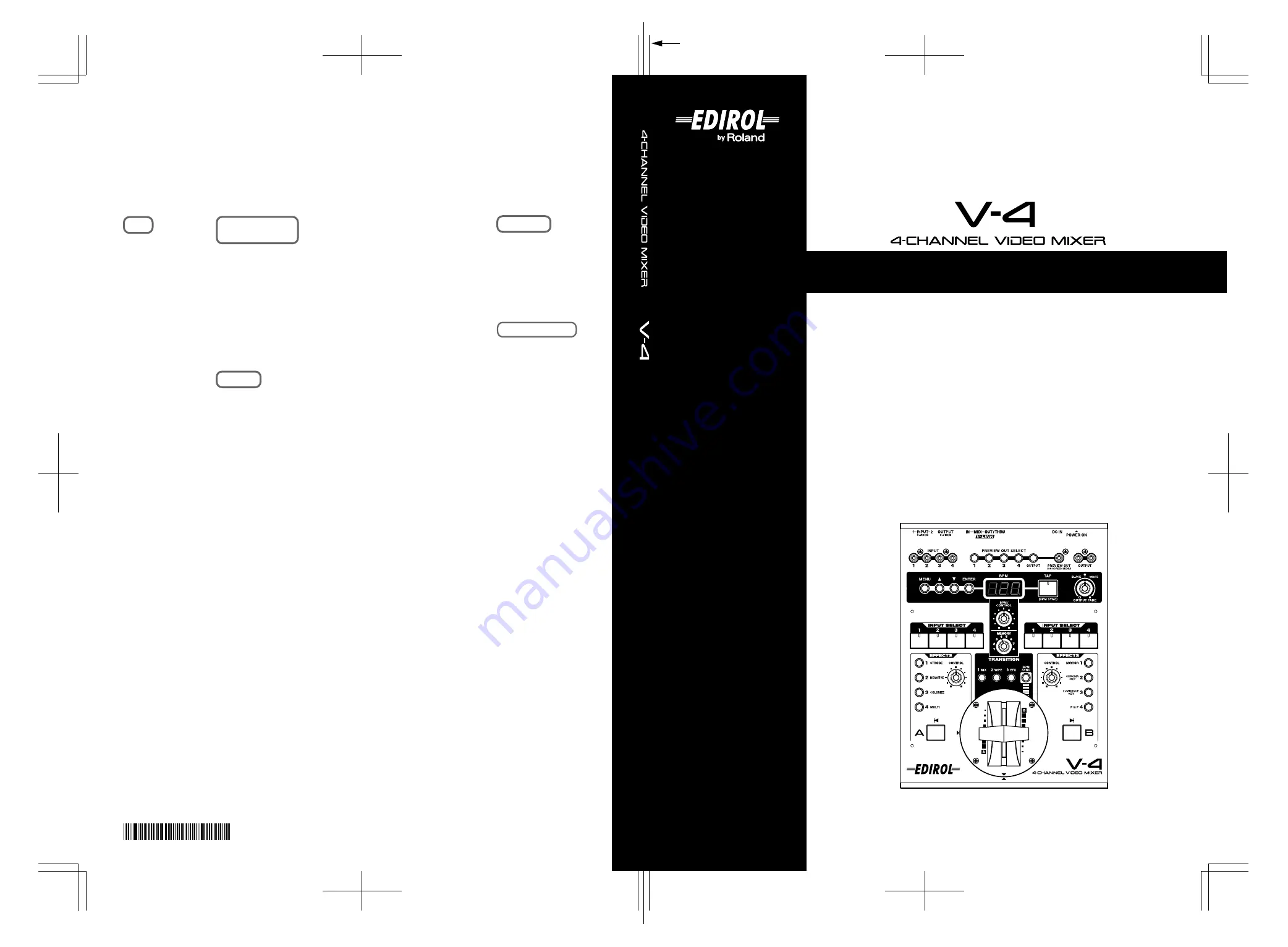
background image


Owner's Manual


Before using this unit, carefully read the sections entitled: “USING THE UNIT SAFELY” 
and “IMPORTANT NOTES” (Owner’s Manual p. 3–4; Owner’s Manual p. 5–6). These 
sections provide important information concerning the proper operation of the unit. 
Additionally, in order to feel assured that you have gained a good grasp of every 
feature provided by your new unit, Owner’s manual should be read in its entirety. The 
manual should be saved and kept on hand as a convenient reference.

Copyright © 2003  ROLAND CORPORATION

All rights reserved. No part of this publication may be reproduced in any form without 
the written permission of ROLAND CORPORATION.


03019190          07-11-5N


Owner’s Manual


To resize thickness, move all items on the front cover

and center registration marks to left or right

Information

When you need repair service, call your nearest EDIROL/Roland Service Center or authorized EDIROL/Roland distributor 
in your country as shown below.

As of Oct. 1, 2007 

 (EDIROL-2)

ASIA

INDONESIA

PT. Citra IntiRama

JL. Cideng Timur No. 15J-15O 
Jakarta Pusat
INDONESIA
TEL: (021) 632-4170

CHINA

Roland Shanghai Electronics Co.,Ltd.

5F. No.1500 Pingliang Road 
Shanghai 200090, CHINA
TEL: (021) 5580-0800

Roland Shanghai Electronics Co.,Ltd.
(BEIJING OFFICE)

10F. No.18 3 Section Anhuaxili 
Chaoyang District Beijing 
100011 CHINA
TEL: (010) 6426-5050

KOREA

KOREA AVICS CO., LTD.

463-3 Sunghwa bldg. 3rd F.,
Seokyo-Dong, Mapo-ku,
Seoul, KOREA
Tel: 02-322-3264

TAIWAN

ROLAND TAIWAN 
ENTERPRISE CO., LTD.

Room 5, 9fl. No. 112 Chung Shan 
N.Road Sec.2, Taipei, TAIWAN, 
R.O.C.
TEL: (02) 2561 3339

SINGAPORE/
MALAYSIA

Roland Asia Pacific Sdn. Bhd.

45-1, Block C2, Jalan PJU 1/39, 
Dataran Prima, 47301 Petaling 
Jaya, Selangor, MALAYSIA
TEL: 3-7805-3263

CENTRAL/LATIN
AMERICA

CZECH REP.

CZECH REPUBLIC 
DISTRIBUTOR s.r.o

Voctárova 247/16
CZ - 180 00 PRAHA 8,
CZECH REP.
TEL: (2) 830 20270

DENMARK

Roland Scandinavia A/S

Nordhavnsvej 7, Postbox 880,
DK-2100 Copenhagen
DENMARK 
TEL: 3916 6200

FINLAND

Roland Scandinavia As, 
Filial Finland

Elannontie 5
FIN-01510 Vantaa, FINLAND
TEL: (0)9 68 24 020

NORWAY

Roland Scandinavia Avd. 
Kontor Norge

Lilleakerveien 2 Postboks 95 
Lilleaker N-0216 Oslo 
NORWAY
TEL: 2273 0074

SWEDEN

Roland Scandinavia A/S 
SWEDISH SALES OFFICE

Danvik Center 28, 2 tr. 
S-131 30 Nacka SWEDEN 
TEL: (0)8 702 00 20 

BRAZIL

Roland Brasil Ltda.

Rua San Jose, 780 Sala B
Parque Industrial San Jose
Cotia - Sao Paulo - SP, BRAZIL
TEL: (011) 4615 5666  

Other CENTRAL/ 

LATIN AMERICA

Roland Systems Group U.S.

425 Sequoia Drive Suite 114, 
Bellingham, Washington, 
98226 USA
TEL: 360-594-4282

AUSTRIA/GERMANY/
ITALY/IRELAND/
UNITED KINGDOM

EDIROL (Europe) Ltd. 

Studio 3.4 114 Power Road 
London W4 5PY
U. K.
TEL: (0)20 8747 5949

BELGIUM/FRANCE/
LUXEMBOURG/
SWITZERLAND/
HOLLAND/SPAIN/
PORTUGAL

Roland Iberia, S.L. 

Paseo García Faria, 33-35
08005 Barcelona SPAIN
TEL: 93 493 91 00

CROATIA

ART-CENTAR

Degenova 3.
HR - 10000 Zagreb
TEL: (1) 466 8493

EUROPE

HUNGARY

Roland East Europe Ltd.

Warehouse Area ‘DEPO’ Pf.83
H-2046 Torokbalint,  HUNGARY
TEL: (23) 511011

POLAND

ROLAND POLSKA SP. Z O.O.

UL. Gibraltarska 4.
PL-03 664 Warszawa 
POLAND
TEL: (022) 679 4419

ROMANIA

FBS LINES

Piata Libertatii 1,
535500 Gheorgheni, ROMANIA
TEL: (266) 364 609

RUSSIA

MuTek

Dorozhnaya ul.3,korp.6
117 545 Moscow, RUSSIA 
TEL: (095) 981-4967

SLOVAKIA

DAN Acoustic s.r.o. 

Povazská 18.
SK - 940 01 Nové Zámky
TEL: (035) 6424 330

UKRAINE

EURHYTHMICS Ltd.

P.O.Box: 37-a.
Nedecey Str. 30
UA - 89600 Mukachevo, 
UKRAINE
TEL: (03131) 414-40

Roland Corporation 
Australia Pty., Ltd. 

38 Campbell Avenue 
Dee Why West, NSW 2099 
AUSTRALIA 

For Australia
Tel: (02) 9982 8266
For New Zealand
Tel: (09) 3098 715

CANADA

Roland Canada Ltd.
(Head Office)

5480 Parkwood Way, Richmond 
B. C., V6V 2M4 CANADA 
TEL: (604) 270 6626 

Roland Canada Ltd.
(Toronto Office)

170 Admiral Boulevard
Mississauga ON L5T 2N6 
CANADA 
TEL: (905) 362 9707  
 

U. S. A.

Roland Systems Group U.S.

425 Sequoia Drive Suite 114, 
Bellingham, Washington, 
98226 USA
TEL: 360-594-4282

NORTH AMERICA

OCEANIA


*

0

3

0

1

9

1

9

0

-

0

5

*

Summary of Contents for V-4

Page 1: ...via A S Nordhavnsvej 7 Postbox 880 DK 2100 Copenhagen DENMARK TEL 3916 6200 FINLAND Roland Scandinavia As Filial Finland Elannontie 5 FIN 01510 Vantaa FINLAND TEL 0 9 68 24 020 NORWAY Roland Scandinavia Avd Kontor Norge Lilleakerveien 2 Postboks 95 Lilleaker N 0216 Oslo NORWAY TEL 2273 0074 SWEDEN Roland Scandinavia A S SWEDISH SALES OFFICE Danvik Center 28 2 tr S 131 30 Nacka SWEDEN TEL 0 8 702 0...

Page 2: ...ct the interference by one or more of the following measures Reorient or relocate the receiving antenna Increase the separation between the equipment and receiver Connect the equipment into an outlet on a circuit different from that to which the receiver is connected Consult the dealer or an experienced radio TV technician for help This device complies with Part 15 of the FCC Rules Operation is su...

Page 3: ...ate the unit 012b Immediately turn the power off remove the AC adaptor from the outlet and request servicing by your retailer the nearest Roland Edirol Service Center or an authorized Roland Edirol distributor as listed on the Information page when The AC adaptor the power supply cord or the plug has been damaged or If smoke or unusual odor occurs Objects have fallen into or liquid has been spille...

Page 4: ... and clean it by using a dry cloth to wipe all dust and other accumulations away from its prongs Also disconnect the power plug from the power outlet whenever the unit is to remain unused for an extended period of time Any accumulation of dust between the power plug and the power outlet can result in poor insulation and lead to fire 104 Try to prevent cords and cables from becoming entangled Also ...

Page 5: ...hours until the condensation has completely evaporated Maintenance 401a For everyday cleaning wipe the unit with a soft dry cloth or one that has been slightly dampened with water To remove stubborn dirt use a cloth impregnated with a mild non abrasive detergent Afterwards be sure to wipe the unit thoroughly with a soft dry cloth 402 Never use benzine thinners alcohol or solvents of any kind to av...

Page 6: ...17 turn on power to your various devices in the order specified By turning on devices in the wrong order you risk causing malfunction and or damage to other devices 942 This unit is equipped with a protection circuit A brief interval a few seconds after power up is required before the unit will operate normally About specifications 962a In the interest of product improvement the specifications and...

Page 7: ...ing the power off 19 Checking the inputs and outputs 20 Checking the final output 20 Checking the output to the preview monitor 20 About the display on preview monitor 21 About the Memory dial MEMORY 22 Switching two images 23 Switching by Cut 23 Switching with dissolve 24 Switching with Wipe 24 Using fade to white or fade to black 25 Compositing two images 26 Using Picture In Picture to composite...

Page 8: ...ctory settings 55 Control the V 4 from an external device 57 Using V LINK to control the V 4 57 Using MIDI to control the V 4 58 Making various settings 64 Calibrating the video fader 66 Using the V 4 in Presentation mode 68 What is Presentation mode 68 Switching to Presentation mode 69 Presentations using two screens with Picture In Picture 69 Switching between NTSC and PAL 71 Changing the video ...

Page 9: ...and easy operation the V 4 allows performances and presentations that include images to be made more expressive than ever before The V 4 can also be controlled from external MIDI devices Images projected on the stage can be controlled while you play an instrument adding impressive impact to a stage performance We hope you will enjoy the V 4 s versatile video functionality in a wide range of applic...

Page 10: ...e In Picture Mirror and Multi can be independently applied to both channels A and B Simple operation Switching and mixing video sources is extremely easy The T bar type video fader can be installed in either the horizontal or vertical orientation whichever you prefer Preview function Before switching sources you can use a preview TV screen to view the images being input on each channel without aff...

Page 11: ...ide range of visual effects that are linked to the expressive elements of a music performance Roland Edirol product that supports V LINK Roland Edirol product that supports V LINK Remote control Remote control Audio output Audio output Mixer speaker Mixer speaker Video output Video output TV projector etc TV projector etc DV 7PR Presenter running V LINK V LINK V 4 V 4_e book 11 ページ 2007年10月17日 水曜日...

Page 12: ...e included items The V 4 is shipped with the following items Please make sure that nothing is missing 1 The V 4 itself 2 AC adaptor and power cable 3 Owner s manual 4 Four screws to affix Video Fader spare V 4_e book 12 ページ 2007年10月17日 水曜日 午後7時15分 ...

Page 13: ...ECT 10 Preview output jack PREVIEW OUT 11 Video composite output jacks OUTPUT 12 Parameter setting buttons 13 BPM indicator 14 Tap button TAP 15 Output fade dial OUTPUT FADE 16 Channel A input selector INPUT SELECT 17 BPM control dial BPM CONTROL 18 Memory dial MEMORY 19 Channel B input selector INPUT SELECT 20 Channel A effect buttons EFFECTS 21 Channel A effect control dial CONTROL 22 Channel A ...

Page 14: ...e buttons select the image that will be output to the preview monitor You can select one of the input signals of channels 1 through 4 or the mixed output signal 10 Preview output jack PREVIEW OUT This jack outputs the preview monitor signal Simultaneously MIDI and effect parameters are also output to the preview monitor 11 Video composite output jacks OUTPUT These jacks output video composite sign...

Page 15: ...effect that is being applied to the image of channel A The dial will adjust an effect parameter of the effect button that is blinking 22 Channel A transformer button TRANSFORMER see p 23 This button lets you switch between channel A and B without using the video fader With the factory settings the switch to the channel A image will be instant You can also change the settings to make the change occ...

Page 16: ...rameter of the effect button that is blinking 30 Channel B transformer button TRANSFORMER see p 23 This button lets you switch between channels A and B without using the video fader About Ground Terminal In some cases depending on the environment in which the unit is installed the surface of the panel may sometimes feel rough and grainy This is due to an infinitesimal electrical charge which is ab...

Page 17: ...io outputs can be connected directly to speakers or via an audio mixer if mixing of audio from multiple devices is necessary No video cables come with this product Please use appropriate video cables for connection with source devices or TV monitor Projector It is recommended to use composite cable rather than S video cable where you need to connect devices long distances unless using S video ampl...

Page 18: ... menus like effect parameters are displayed on preview monitor If both video composite and S video signals are input simultaneously to the same channel channel 1 or 2 only the S video signal will take priority When switching on Preview Selector is done image on preview monitor may flicker briefly This does not affect image from output jacks Camcorder VCR Input selector Channel A Channel B Video mi...

Page 19: ...five seconds for the V 4 to initialize itself and begin operating To prevent the inadvertent disruption of power to your unit should the plug be pulled out accidentally and to avoid applying undue stress to the AC adaptor jack anchor the power cord using the cord hook as shown in the illustration Turning the power off 1 Press the POWER button Press the POWER button located on the rear panel of the...

Page 20: ...r Successively press buttons 1 through 4 to switch inputs Confirm that the image shown on your TV monitor or projector changes accordingly Checking the output to the preview monitor Next you should check whether the image is being correctly output to the preview TV monitor 1 Play back your source device Operate the source device e g camcorder VCR DVD player DV 7PR connected to the V 4 so it output...

Page 21: ...played aside highlighted effect names it means the effect parameter can be changed with the control dial You can add or reduce the information displayed on the preview monitor by changing the settings of the V 4 as described on p 75 or later Preset is displayed when position 1 of Memory Dial is selected The 1st setting is fixed to the factory preset and cannot be changed Protect On is displayed wh...

Page 22: ...eptual diagram of the Memory dial Number 1 is fixed at the factory settings Numbers 2 8 can store the function panel setting assigned to the various buttons and dials These buttons let you change the pattern of the transition effects For details on how to change these refer to p 40 It is also possible to store setting of BPM Sync mode You can change the setting of the Output Fade dial For details ...

Page 23: ...y change when you switch between channels For example if you have selected input image 1 for channel A you should choose from images 2 through 4 for channel B 3 Output either channel A or channel B Move the video fader all the way to the channel A or channel B position Watch the final output on your TV monitor or projector 4 Press a transformer button TRANSFORMER If you have moved the video fader ...

Page 24: ...be input to channel A and channel B If the same image is being input to both A and B channels you will not notice any change when you switch between channels For example if you have selected input image 1 for channel A you should choose from images 2 through 4 for channel B 3 Press the mix button MIX Press the mix button MIX located above the video fader The button will light 4 Move the video fade...

Page 25: ...V 4 you can fade an image to white or black simply by turning a dial If you fade to white the monitor output image will gradually turn white If you fade to black the monitor output image will gradually turn black 1 Set the memory dial MEMORY to 1 Turn the dial all the way to the left to the 1 position 2 Output an image Output an image from a source device If desired you may stop the video fader in...

Page 26: ... the background image into channel A Use the channel A input select buttons to make your choice 4 Select the channel B input Input the image that you want to miniaturize into channel B Use the channel B input select buttons to make your choice 5 Press the P in P button Press the channel B P in P button 6 Move the video fader Moving the video fader will control the level of the channel B image the ...

Page 27: ...elect the 1 position 2 Select channel A image Play back the image that you want to use as the background 3 Select channel B image Input image to overlay into channel B The image for Chroma Key is generally shot with blue or green background 4 Press the Chroma Key button Press the channel B Chroma Key button 5 Move the video fader to channel B The blue part of channel B image is extracted and the c...

Page 28: ...is called Luminance Key Here s how you can composite image from channel B and overlay it on the channel A image 1 Set the memory dial MEMORY to 1 Turn the dial all the way to the left to select the 1 position Some effects cannot be used simultaneously You cannot composite images if you image has no consistent color that can be extracted with Chroma Key It is also difficult to extract correctly if ...

Page 29: ...annel B The light or dark part of the channel B image is extracted and the image from channel A appears 6 Turn the control dial Parameter of Luminance Key level of extraction gradually changes If Luminance Key button is not blinking you cannot change the parameter with control dial 7 Move the video fader Moving the video fader will control appearance and disappearance of image after extraction 8 T...

Page 30: ...t correctly if contrast of light dark is not sufficient or consistent The default status of the Luminance Key of V 4 is set to extract the light part of the image It is possible to change setting to extract dark part It is also possible to adjust the extraction level of blur level of edges For details refer to p 75 or later V 4_e book 30 ページ 2007年10月17日 水曜日 午後7時15分 ...

Page 31: ...ct the 1 position 2 Play back the image to which you want to apply the effect Play back the desired image and input it to the V 4 3 Select the input for channel A Input the image being played back into channel A Use the channel A input select buttons to make your choice 4 Move the video fader to channel A To output the image of channel A move the video fader to channel A 5 Press the NEGATIVE butto...

Page 32: ...ich you want to apply the effect Play back the image that you want to colorize and input it to the V 4 3 Select the input for channel A Input the image being played back into channel A Use the channel A input select buttons to make your choice 4 Move the video fader to channel A To output the image of channel A move the video fader to channel A 5 Press the COLORIZE button Press the channel A COLOR...

Page 33: ...ative and Colorize effects the color of the image can also be modified using the Posterize effect To use the Posterize effect you will need to assign it to an effect button of channel A or channel B For details on making this assignment refer to p 75 or later V 4_e book 33 ページ 2007年10月17日 水曜日 午後7時15分 ...

Page 34: ...el A input select buttons to make your choice 4 Move the video fader to channel A To output the image of channel A move the video fader to channel A 5 Press the STROBE button Press the channel A STROBE button This is the top effect button on the channel A side 6 Turn the control dial Turn the control dial The strobe settings will be adjusted and the spacing of the frames will change from fast to s...

Page 35: ...Use the channel A input select buttons to make your choice 4 Move the video fader to channel A To output the image of channel A move the video fader to channel A 5 Press the MULTI button Press the channel A MULTI button This is the bottom effect button on the channel A side With the factory settings the image will be divided in the XX direction 6 Turn the control dial Turn the control dial The mul...

Page 36: ...put select buttons to make your choice 4 Move the video fader to channel B To output the image of channel B move the video fader to channel B 5 Press the MIRROR button Press the channel B MIRROR button This is the top effect button on the channel B side With the factory settings the image will be inverted in the XX direction 6 Turn the control dial Turn the control dial The mirror effect parameter...

Page 37: ...operate the video fader or the transformer buttons 1 Input images to channels A and B Use the channel A and B input selectors to input images into each channel Input different images into channels A and B 2 Set the BPM Turn the BPM control dial BPM CONTROL to set the BPM Smaller values will cause the images to be switched more slowly and greater values will cause faster switching 3 Press the BPM s...

Page 38: ...each channel Input different images into channels A and B 2 Press the BPM sync button BPM SYNC Press the BPM sync button The images will begin switching at the BPM timing shown in the BPM indicator 3 Press the tap button TAP in time with the music Play back the desired background music and press the tap button in time with the beat The BPM readout will be constantly updated to reflect the timing y...

Page 39: ...ss the BPM sync button Notice that the effect is applied to the image in synchronization with the BPM you specified You may also turn the BPM dial at this time to adjust the timing Using the tap TAP function to apply an effect As an alternative to specifying the BPM numerically you can use the tap button TAP to manually specify the timing at which the effect will be switched on off In this case yo...

Page 40: ...rmer buttons TRANSFORMER Channel B transformer buttons TRANSFORMER Settings and menu information is displayed on the TV monitor connected to the preview output If you need to change settings the operation can be executed by viewing the information and menu displayed on the preview monitor You can change settings by using the following buttons Menu Button MENU When pressed the button lights up and ...

Page 41: ...41 Editing the front panel assignments V 4_e book 41 ページ 2007年10月17日 水曜日 午後7時15分 ...

Page 42: ... Press the mix button MIX The button lights up when pressed 3 Press the menu button MENU Press the menu button MENU located in the upper left of the panel The settings edit menu will appear on the TV screen connected to the preview output 4 Select MIX Use the cursor buttons to select Mix Trans1 It will blink when you select it The memory dial number you select is displayed following Mix Trans1 If ...

Page 43: ...f the memory dial Here s how to assign a different type of transition effect to the wipe button 1 Set the memory dial to the number whose assignment you want to change Operate the video fader while you turn the memory dial to different positions Notice how the dial selects different wipe patterns Set the memory dial to the number 2 through 8 whose settings you want to change 2 Press the wipe butto...

Page 44: ...ed an effect press the menu button to return to the previous screen Press the button twice to exit the menu screen and return to the previous screen Changing the assignment of the EFX button EFX With the factory settings various special wipes and basic slides are assigned to this button for the eight settings of the memory dial Here s how to assign a different type of transition effect to the EFX ...

Page 45: ... you select is displayed following EFX If you have selected memory number 2 this will indicate Mem2 5 Press the enter button ENTER Press the enter button located at the right of the cursor buttons to make your selection The preview screen display will change 6 Select the transition effect Use the cursor buttons to select the type of transition effect With an effect selected blinking and the video ...

Page 46: ... 1 Set the memory dial to the number whose assignment you want to change Operate the output fade dial while you turn the memory dial to different positions Set the memory dial to the number 2 through 8 whose settings you want to change 2 Press the menu button MENU Press the menu button MENU located in the upper left of the panel The settings edit menu will appear on the TV screen connected to the ...

Page 47: ...de pattern With a pattern selected blinking turn the output fade dial to see the currently selected fade pattern occur in the output screen If you select No Control turning the dial in either direction will not produce a fade 6 Return to the previous screen When you have selected a fade pattern press the menu button to return to the previous screen Press the button twice to exit the menu screen an...

Page 48: ...gnment you want to change Press the effect button channel A buttons 1 4 channel B buttons 1 4 whose assignment you want to change The effect will be applied 3 Press the menu button MENU Press the menu button MENU located in the upper left of the panel The settings edit menu will appear on the TV screen connected to the preview output 4 Select either Effects A or Effects B Select Effects A if you w...

Page 49: ...een will show A Efx1 through A Efx4 If you have selected channel B the screen will show B Efx1 through B Efx4 Select the button whose assignment you want to change For example if you want to change the assignment of channel A button 2 you would select A Efx2 Press the enter button to go to the effect setting screen 7 Select the type of effect Use the cursor buttons to select the effect that you wa...

Page 50: ... Turn the memory dial Select the memory number 2 through 8 whose assignments you want to change 2 Press the menu button MENU Press the menu button MENU located in the upper left of the panel The settings edit menu will appear on the TV screen connected to the preview output 3 Select BPM SYNC Use the cursor buttons to select BPM SYNC The memory dial number you select is displayed following BPM SYNC...

Page 51: ...een When you have finished making settings press the menu button to return to the previous screen Press the button three times to exit the menu screen and return to the previous screen Changing the assignment of the channel A channel B transformer buttons TRANSFORMER With the factory settings and when the memory dial is set to 1 the switch to image A or B takes place immediately when you press the...

Page 52: ... the parameter to be assigned 5 Select a pattern Select a pattern from the range of 01 none none to 36 Black White If you select 01 none none the transformer buttons will have no effect you will not be able to switch between images A B or fade to white black by pressing these buttons For details on the operation and times of these parameters refer to the menu list on p 78 6 Return to the previous ...

Page 53: ...review output 2 Select Utility Use the cursor buttons to select Utility Then press the enter button ENTER to move to the following screen 3 Select Memory Protect Use the cursor buttons to select Memory Protect Then press the enter button ENTER to move to the following screen 4 Turn the setting On Use the cursor buttons to select On or Off Selecting On turns memory protection on so you will be unab...

Page 54: ... memory 1 Press the menu button MENU Press the menu button The menu will appear on the TV screen connected to the preview output 2 Select Memory Edit Use the cursor buttons to select Memory Edit Press the enter button ENTER to move to the following screen 3 Select the operation Use the cursor buttons to select the operation For example if you want to copy memory number 8 to memory number 2 select ...

Page 55: ...n recall factory settings with the following operation Any change of settings or adjustments you have made will be cleared with this operation Do not execute this function if you want to retain any of your saved settings If it is necessary to execute the recall function you should write down the settings of your memory first 1 Press the menu button MENU Press the menu button The menu will appear o...

Page 56: ...assignments 4 Press the enter button ENTER Pressing the enter button will reinitialize the V4 to its Factory Presets All the settings and adjustments will return to factory preset status V 4_e book 56 ページ 2007年10月17日 水曜日 午後7時15分 ...

Page 57: ... s sequencer to control video switching on the V 4 to create performances that link images with music You can use the MC 909 s velocity pads to control the V 4 s input selectors and switch among images from various source devices You can use the MC 909 s knobs to adjust the time settings of transition effects such as overlap or wipe Example When using an Edirol PCR 30 50 in conjunction with the V ...

Page 58: ...ils on the functions that can be controlled from an external device via V LINK refer to MIDI Implementation p 89 and to the MIDI implementation of the device you have connected The functions that can be controlled will differ depending on the device that is connected and on its settings Using MIDI to control the V 4 You can connect the V 4 with various MIDI devices for a wide range of remote contr...

Page 59: ...ctions of the V 4 Even if you are using a device that does not support V LINK you can make transmission and reception settings so that the V 4 can be controlled from a musical instrument or other external device For details on the functionality that can be controlled via MIDI from an external device refer to p 89 of this manual and to the MIDI implementation of the device you have connected V 4_e ...

Page 60: ... 2 Select MIDI Setup Use the cursor buttons to select MIDI Setup Press the enter button ENTER to enter the MIDI setting screen 3 Select MIDI Tx Channel Use the cursor buttons to select MIDI Tx Channel Press the enter button ENTER to enter the transmit channel setting screen 4 Specify the transmit channel Use the cursor buttons to select the transmit channel 5 Return to the previous screen When you...

Page 61: ...enter button ENTER to enter the MIDI setting screen 3 Select MIDI Rx Channel Use the cursor buttons to select MIDI Rx Channel Press the enter button ENTER to enter the receive channel setting screen 4 Specify the receive channel Use the cursor buttons to select the receive channel 5 Return to the previous screen When you have finished making settings press the menu button to return to the previous...

Page 62: ...g buttons and dials can be controlled via MIDI Channel A effect buttons 1 4 Channel B effect buttons 1 4 Video fader Channel A B transformer buttons BPM SYNC button Output fader In addition the duration of a transition effect can also be controlled via MIDI Refer to the following table for more about MIDI settings V 4_e book 62 ページ 2007年10月17日 水曜日 午後7時15分 ...

Page 63: ...trols the duration of the transition effect MIDI message that operates the output fader MIDI Tx Channel MIDI Tx Channel MIDI Out Thru Switch V LINK Switch Note Mode On Off Device ID Effects A1 Assign Effects A2 Assign Effects A3 Assign Effects A4 Assign Effects B1 Assign Effects B2 Assign Effects B3 Assign Effects B4 Assign Video Fader Assign Transition Assign Transformer A Assign Transformer B As...

Page 64: ...n also use the same procedure to change the output position of the image or switch the video fader mode 1 Press the menu button Press the menu button MENU The menu will appear in the preview screen 2 Select Utility Use the cursor buttons to select Utility Press the enter button ENTER to move to the following screen 3 Select the item that you want to set Use the cursor buttons to select the item th...

Page 65: ... screen When you have finished making the setting press the menu button to return to the previous screen If you press the menu button three times you will exit the menu screens and return to the previous screen V 4_e book 65 ページ 2007年10月17日 水曜日 午後7時15分 ...

Page 66: ...setting Move the video fader all the way to the A position 2 Press the menu button MENU Press the menu button to display the menu in the preview screen 3 Select Utility Use the cursor buttons to select Utility Then press the enter button to display the Utility settings 4 Select Video Fader Calibrate A Use the cursor buttons to select Video Fader Calibrate A The display will indicate V Fader A set ...

Page 67: ...e B Use the cursor buttons to select Video Fader Calibrate B The display will indicate V Fader B set ENTER SW 10 Press the enter button ENTER Press the enter button The channel B position will be calibrated automatically 11 Return to the previous screen When you are finished press the menu button to return to the previous screen If you press the menu button twice you will exit the menu screens and...

Page 68: ...annel A input selector to switch sources the selected transition effect will automatically be applied Ach Bch The duration of the transition effect is shown in the BPM indicator Use the BPM control dial to adjust the duration Use the video fader to control the level of image B Use the memory dial to select the effect applied to the channel B image The following effects are assigned to the memory n...

Page 69: ...fect If this dial is set to the far left the transition effect will have a duration of 0 seconds If set to the far right the transition effect will have a duration of 4 seconds Presentations using two screens with Picture In Picture Here s how you can composite two screens a technique frequently used in presentations 1 Switch the V 4 to Presentation mode Start up the V 4 in Presentation mode as de...

Page 70: ...n Picture will be applied 4 Apply other effects to composite two images Turn the memory dial to other positions to try out other types of effects Numbers 2 5 change the location of the secondary screen of the Picture In Picture function Numbers 6 8 apply other effects luminance key chroma key 5 Switch the secondary image Press the channel B input selector buttons to switch the secondary image V 4_...

Page 71: ...s the power button The next time you start up you can simply press the power button to start up in PAL mode If you want to return to NTSC mode once again hold down preview select button 1 and OUTPUT and press the power button When the V 4 starts up an indication of whether it is starting up in NTSC mode or PAL mode will appear for several seconds in the preview screen V 4_e book 71 ページ 2007年10月17日...

Page 72: ... screws from the round video fader mounting plate being careful not to lose them 2 Reposition the video fader Turn the video fader 90 degrees Align the triangle printed on the round mounting plate of the video fader with the triangle printed on the panel of the V 4 3 Fasten the screws Fasten the video fader to the panel using the screws that you removed earlier Firmly tighten all four screws The c...

Page 73: ... be damaged Note the location of the triangle symbols and do not rotate the video fader panel further than 90 degrees To remove the screws use a screwdriver that matches the screw heads and work carefully If the screw heads become damaged you will be unable to fasten the video fader in place V 4_e book 73 ページ 2007年10月17日 水曜日 午後7時15分 ...

Page 74: ...so make sure that the input select setting is correct Turning the control dial does not change the effect Not all effects have parameters that can be modified by the control dial If you have selected an effect whose parameter can be modified by the control dial the channel A B effect button will blink If the button is only lit not blinking the control dial will not affect the parameter Image does ...

Page 75: ...er of effects marked by an asterisk can be varied by the control dial 01 STILL1 02 STILL2 03 STROBE1 12 STROBE 13 SHAKE1 16 SHAKE4 17 NEGATIVE1 20 NEGATIVE 21 COLRIZE1 29 COLRIZE 30 MONOCOLOR1 38 MONOCOLOR 39 POSTERIZE1 43 POSTERIZE 44 COLORPASS1 52 COLORPASS 53 W LUMIKEY 54 W LUMIKEY 55 B LUMIKEY 56 B LUMIKEY Still Strobe Shake Negative inverted brightness and color Colorize apply colors to the i...

Page 76: ...ltiscreen Horizontal mirroring Vertical mirroring Horizontal and vertical mirroring White LumiKey Level White LumiKey Edge Black LumiKey Level Black LumiKey Edge ChromaKey Color ChromaKey Level ChromaKey Edge 000 255 001 015 000 255 001 015 000 255 001 015 Blue Magenta Yellow Red Adjust the level of luminance key extraction extract white Adjust the edge blurring for luminance key extract white Adj...

Page 77: ...osi 207 4 3 HVSize 000 4 3 HVSize 110 HSize 000 HSize 110 VSize 000 VSize 220 Border 000 Border 015 BColor 000 BColor 015 Shadow 000 Shadow 015 SColor 000 SColor 015 Adjust horizontal location of PinP Adjust vertical location of PinP Adjust size at fixed aspect ratio of 4 horizontal 3 vertical Adjust horizontal size of PinP Adjust vertical size of PinP Select border width of PinP Select border col...

Page 78: ...between A and B each time you press the button 0 9 indicates the duration of the transition Higher numbers produce a longer transition Switch to the image of the channel A or B you press 0 9 indicates the duration of the transition Higher numbers produce a longer transition Switch to the image of the opposite channel A or B from the one you press 0 9 indicates the duration of the transition Higher...

Page 79: ...ze at fixed aspect ratio of 4 horizontal 3 vertical Adjust horizontal size of PinP Adjust vertical size of PinP Select border width of PinP Select border color of PinP Select distance of PinP shadow Select color of PinP shadow PinP1 Setup PinP2 Setup PinP3 Setup PinP4 Setup PinP5 Setup PinP6 Setup PinP7 Setup PinP8 Setup White LumiKey Level White LumiKey Edge Black LumiKey Level Black LumiKey Edge...

Page 80: ...perates the Transformer A button MIDI message that operates the Transformer B button MIDI message that operates the BPM SYNC button MIDI message that controls the duration of the transition effect MIDI message that operates the output fader MIDI Tx Channel MIDI Tx Channel MIDI Out Thru Switch V LINK Switch Note Mode On Off Device ID Effects A1 Assign Effects A2 Assign Effects A3 Assign Effects A4 ...

Page 81: ... Operate in Presentation mode Memory protect is off Memory protect is on Adjust video synchronization sensitivity Adjust the brightness of channel A Adjust color of channel A Adjust hue of channel A Adjust the brightness of channel B Adjust color of channel B Adjust hue of channel B Adjust horizontal location of video output Adjust vertical location of video output Adjust width horizontal of video...

Page 82: ...vel of the output fader Turn off the preview display Specify the mode of the preview display Manually select the preview output Fix the preview output to show inputs 1 4 or the output Automatically switch the preview output Specify the speed of automatic preview output switching Turn off preview checking Turn on preview checking Specify the preview output color when there is no signal Turn off blu...

Page 83: ...chrominance signal 0 286 mVp p 75 ohm NTSC 0 3 mVp p 75 ohm PAL Video composite output 1 Vp p 75 ohm Output level and impedance S video output luminance signal 1 Vp p 75 ohm chrominance signal 0 286 mVp p 75 ohm NTSC 0 3 mVp p 75 ohm PAL Video composite output final output and preview output 1 Vp p 75 ohm Control connectors MIDI IN 5 pin DIN type MIDI OUT 5 pin DIN type Transition effects Mix Diss...

Page 84: ...84 Main specifications Dimensions 225 mm W x 295 mm D x 105 mm H Weight 2 3 kg Included items AC adaptor Owner s manual T bar attachment screws x 4 pcs spares V 4_e book 84 ページ 2007年10月17日 水曜日 午後7時15分 ...

Page 85: ...t events such as exhibitions or performances Live source Video images Preview Large display plasma Projector Advantages of using the V 4 Two images two live images or live video recorded video can be mixed Use picture in picture to display two screens simultaneously For details on switching images refer to p 23 For details on using picture in picture refer to p 26 V 4_e book 85 ページ 2007年10月17日 水曜日...

Page 86: ...the DV 7PR can be mixed with multiple live images Live source DV 7PR Video output Preview Projector 1 Projector 2 Advantages of using the V 4 Use BPM TAP to switch images in time with the music Use numerous effects such as mirror strobe or colorize For details on using BPM TAP refer to p 37 For details on using strobe refer to p 34 For details on using colorize refer to p 32 V 4_e book 86 ページ 2007...

Page 87: ...nvert the computer s VGA output into a video signal Live source PC DVD Preview Large display plasma Projector Advantages of using the V 4 Use picture in picture to display two screens simultaneously Use luminance key to superimpose text or graphics on the image Easy operation in Presentation mode For details on using picture in picture refer to p 26 For details on using luminance key refer to p 28...

Page 88: ...le button to quickly and easily make settings for controlling images Live source DV 7PR Video output Preview MIDI control Projector 1 Projector 2 Advantages of using the V 4 When used in conjunction with the DV 7PR a single instrument can control the live video and the video from the DV 7PR Video effects can be turned on off from the musical instrument If you are using a V LINK compatible device M...

Page 89: ...ived Bank Select data that is received will be maintained until a subsequent Bank Select is received These messages select inputs for each channel set memories and specify how the sub channel is mixed in Presentation mode Controls correspond to bank select messages as follows Bank Select Program No Control MSB LSB 50H 00H 00H 07H MEMORY 1 8 00H 00H 00H 03H A ch INPUT 1 4 01H 00H 00H 03H B ch INPUT...

Page 90: ...form reception error processing and will then stop monitoring the message interval Timing Clock Status F8H Used to synchronize BPM SYNC Start Status FAH Specifies the beginning of the beat for BPM SYNC Continue Status FBH Specifies the beginning of the beat for BPM SYNC System exclusive messages Status Data bytes Status F0H iiH ddH eeH F7H F0H System Exclusive Message status ii ID number An ID num...

Page 91: ...t Control 2 controller number 13 Status 2nd byte 3rd byte BnH 0DH vvH General Purpose Controllers 1 4 controller numbers 16 19 Status 2nd byte 3rd byte BnH 10H 13H vvH Hold 1 controller number 64 Status 2nd byte 3rd byte BnH 40H xxH Portamento controller number 65 Status 2nd byte 3rd byte BnH 41H xxH Sostenuto controller number 66 Status 2nd byte 3rd byte BnH 42H xxH Soft controller number 67 Stat...

Page 92: ...01H 05H 07H 1FH Control Change 40H 5FH D0H E0H EFH Channel Press Pitch Bend OFF 01H 10H 08H Tx Rx Setting Transformer B 01H 05H 07H 1FH Control Change 40H 5FH D0H E0H EFH Channel Press Pitch Bend OFF 01H 10H 0AH Tx Rx Setting Output Fade 01H 05H 07H 1FH Control Change 40H 5FH D0H E0H EFH Channel Press Pitch Bend OFF 01H 10H 0CH Tx Rx Setting BPM sync 01H 05H 07H 1FH Control Change 40H 5FH D0H E0H ...

Page 93: ...Rx Setting Transition Select 01H 05H 07H 1FH Control Change 40H 5FH D0H E0H EFH Channel Press Pitch Bend OFF 10H 10H 12H V LINK Rx Setting Transformer A 01H 05H 07H 1FH Control Change 40H 5FH D0H E0H EFH Channel Press Pitch Bend OFF 10H 10H 14H V LINK Rx Setting Transformer B 01H 05H 07H 1FH Control Change 40H 5FH D0H E0H EFH Channel Press Pitch Bend OFF 10H 10H 16H V LINK Rx Setting BPM Sync 01H ...

Page 94: ...0 x 128 0 64 x 128 0 5120 8182 3072 If the Pitch Bend Sensitivity is set to two semitones a pitch change of 8192 00H 00H would change the pitch by 200 cents so in this case a pitch bend of 200 x 3072 8192 75 cents is being designated on MIDI channel 11 Exclusive message examples and checksum calculation Roland exclusive messages RQ1 DT1 contain a checksum following the data after F7 which can be u...

Page 95: ...ion 2 and Transition 3 Transformer A Turns channel A TRANSFORMER on off With the factory settings this is unassigned Values are 0 63 and 64 127 corresponding to OFF and ON Transformer B Turns channel B TRANSFORMER on off With the factory settings this is unassigned Values are 0 63 and 64 127 corresponding to OFF and ON Output Fade Controls OUTPUT FADE With the factory settings this is unassigned V...

Page 96: ... Bend O O Control Various Values Control Change 0 32 1 5 7 31 64 95 O O O O O O O O Bank Select Control Various Values Control Various Values Control Various Values Program Change True Basic Channel O 0 3 0 7 O 0 3 0 7 Input select 1 4 Memory Select 1 8 System Exclusive X O Control Various Values V LINK Common Song Pos Song Sel Tune X X X X X X Real Time Clock Commands X X O O Start Continue Other...

Page 97: ...97 Transition Effects List Factory default Transition effects assignments Factory default Transition effects assignments V 4_e book 97 ページ 2007年10月17日 水曜日 午後7時15分 ...

Page 98: ... Effects The effect gradually blends the picture into another Wipe Effects The effects like windshield wiper on a car The present picture is wiped off as it changes to another Hard Edge type V 4_e book 98 ページ 2007年10月17日 水曜日 午後7時15分 ...

Page 99: ...99 Transition Effects List Soft Edge Type V 4_e book 99 ページ 2007年10月17日 水曜日 午後7時15分 ...

Page 100: ...100 Transition Effects List V 4_e book 100 ページ 2007年10月17日 水曜日 午後7時15分 ...

Page 101: ...101 Transition Effects List Multi Border Type V 4_e book 101 ページ 2007年10月17日 水曜日 午後7時15分 ...

Page 102: ...nother The dark part of B ch picture gradually changes to A ch picture The bright part of A ch picture gradually changes to B ch picture The blight part of B ch picture gradually changes to A ch picture The dark part of A ch picture gradually changes to B ch picture V 4_e book 102 ページ 2007年10月17日 水曜日 午後7時15分 ...

Page 103: ...103 Transition Effects List Slide Effects The effect to slide out the preset picture and in the anothser Normal Type Sequential Type V 4_e book 103 ページ 2007年10月17日 水曜日 午後7時15分 ...

Page 104: ...104 Transition Effects List The effects tha cannot be used simultanously V 4_e book 104 ページ 2007年10月17日 水曜日 午後7時15分 ...

Page 105: ...ist 75 MIDI Rx Channel 61 MIDI settings 60 MIDI Tx Channel 60 Mirror 36 Mix button 15 motion 34 Multi 35 N Negative 31 NTSC 71 O Output fade dial 14 P PAL 71 panel assignments 40 PCR 30 50 57 Picture In Picture 26 Presentation mode 68 preview monitor 21 Preview select buttons 14 Protecting the memory 53 S signal flow 18 specifications 83 strobe motion 34 S video 14 synchronization 37 T tap TAP fun...

Page 106: ...106 Index MEMO V 4_e book 106 ページ 2007年10月17日 水曜日 午後7時15分 ...

Page 107: ...107 Index MEMO V 4_e book 107 ページ 2007年10月17日 水曜日 午後7時15分 ...

Page 108: ...108 Index MEMO V 4_e book 108 ページ 2007年10月17日 水曜日 午後7時15分 ...

Page 109: ...109 Index MEMO V 4_e book 109 ページ 2007年10月17日 水曜日 午後7時15分 ...

Page 110: ...110 Index MEMO V 4_e book 110 ページ 2007年10月17日 水曜日 午後7時15分 ...

Page 111: ...ct the interference by one or more of the following measures Reorient or relocate the receiving antenna Increase the separation between the equipment and receiver Connect the equipment into an outlet on a circuit different from that to which the receiver is connected Consult the dealer or an experienced radio TV technician for help This device complies with Part 15 of the FCC Rules Operation is su...

Page 112: ...via A S Nordhavnsvej 7 Postbox 880 DK 2100 Copenhagen DENMARK TEL 3916 6200 FINLAND Roland Scandinavia As Filial Finland Elannontie 5 FIN 01510 Vantaa FINLAND TEL 0 9 68 24 020 NORWAY Roland Scandinavia Avd Kontor Norge Lilleakerveien 2 Postboks 95 Lilleaker N 0216 Oslo NORWAY TEL 2273 0074 SWEDEN Roland Scandinavia A S SWEDISH SALES OFFICE Danvik Center 28 2 tr S 131 30 Nacka SWEDEN TEL 0 8 702 0...

Reviews: