Ecolibrium Solar EcoFoot5D, Installation Manual
The Ecolibrium Solar EcoFoot5D is a cutting-edge solar mounting system designed for quick and easy installation. Ensure a seamless setup with our comprehensive Installation Manual, available for free download at our website. Equipped with detailed instructions, this manual guarantees a hassle-free experience, helping you maximize your solar power potential.
Share
Download


Reviews:
No comments
Related manuals for EcoFoot5D

Beoplay M5
Brand: Vebos Pages: 2

TSG
Brand: TabLines Pages: 2

M VESA Tablestand Turn
Large
Brand: Multibrackets Pages: 8

HM2122-L
Brand: Mounting Dream Pages: 11

MPCQ-M44V
Brand: Mustang Pages: 10

ML6802
Brand: Suptek Pages: 2

PRS-4.2 Series
Brand: Park Tool Pages: 4

VisionMount VMPl50A
Brand: Sanus Pages: 38

Gale Force Stand
Brand: Dry Air Pages: 2
PMK-4L
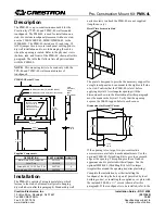
Brand: Crestron Pages: 2

10008385
Brand: IBEX Pages: 2

902-0178-0002
Brand: Ruckus Wireless Pages: 2

RM12 1394B
Brand: Datoptic Pages: 6

ParStor
Brand: Logiquip Pages: 5

PAC-710
Brand: CHIEF Pages: 6

PFC Cart Series
Brand: CHIEF Pages: 8

PAC715
Brand: CHIEF Pages: 8

ODMLT
Brand: CHIEF Pages: 8


